
Modeling the Gemini-B in 1/24 Scale
A Very Short History
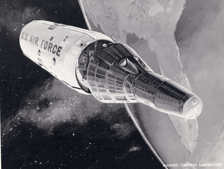
The U.S. Air Force’s Manned Orbital Lab (MOL) project was first announced on December 10, 1963; by Defense Secretary Robert McNamera, at the same press conference he announced the cancellation of the U. S. Air Force’s DynaSoar project. On August 25, 1965, President Johnson announced the formal go-ahead of the project. The program as announced was to consist of two unmanned and five manned flights originating from Vandenberg Air Force Base in California. Douglas was to build the laboratory, McDonnell the Gemini B and General Electric was to manage the experiment package. In 1968, fabrication of the first three flight vehicles (two unmanned and the first manned spacecraft) was undertaken. The entire vehicle was to be launched on a variant of the Titan IIIC called the Titan IIIM. On June 10, 1969, the Deputy Secretary of Defense, David Packard, announced the cancellation of the MOL project on grounds of cost savings and “advances in automated techniques for unmanned satellite systems”. In the interim a total of 1.4 billion dollars had been spent on the Air Force’s Manned Orbital Laboratory space project.

The Gemini-B Vehicle Description
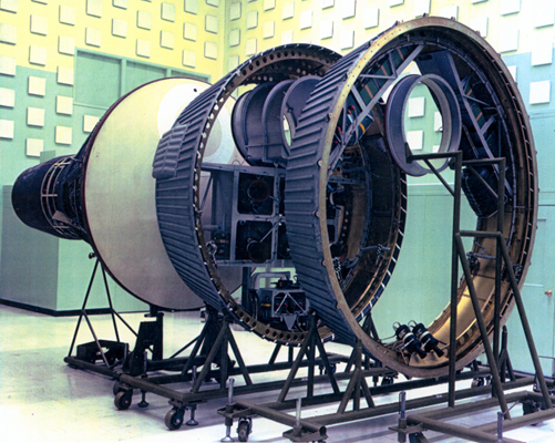
The model depicts the McDonnell portion of the project and consists of the Gemini-B re-entry vehicle and the spacecraft adapter. (A vehicle modified from the NASA Gemini spacecraft which was flown as America’s second manned space program.) Several mockups, trainers and at least one flight article were assembled by McDonnell prior the cancellation of the program. The major changes from NASA’s Gemini included a thicker and slightly wider heat shield. A unique 25.8″ diameter heat shield hatch and a 25″ diameter Large Pressure Bulkhead (LPB) hatch that would allow the astronauts direct, pressurized access to the laboratory portion of the spacecraft. Also modified were the seats, hatch stowage area and instrument panels. The Gemini B Adapter Module was completely different from the NASA Gemini Adapter Module. First off, it was only 54.03″ in height. The forward diameter being the same as the NASA Gemini adapter (88.50″) but the base diameter was 118.35″. (The NASA Gemini adapter was 90.0″ tall, with a base diameter of 120″.) Like the NASA Gemini adapter, the “B” adapter was divided into two sections. However, also unlike the NASA Gemini adapter, the longer section was the retro adapter (at 33.32″). The major internal components included the six retro-rockets and their support structure, a crew transfer tunnel and the environmental control system coolant pump module. The 20.17″ tall equipment adapter included two equipment beams, which supported the main batteries, several “electronic black boxes”, the primary oxygen subsystem and the Gemini-B crew cabin coolant module water tanks. The equipment adapter also housed the pad abort control system separation rockets.
Two kits of the 1993 Revell re-release of the 1/24 scale Gemini Spacecraft model (first released in 1966) were used to create this model.

Crew Cabin – External Changes
Each of the three sections of the crew compartment (parts Nos. 12, 13, 14) needed some amount of modification. On the bottom of part No. 14, the shingled section that includes the slot for the stand was removed and replaced with a similar section from a second kit. The major change on both the left and right crew compartment parts (Nos. 12 & 13) involved lengthening the coves in front of the hatches. This started by placing the hatches in their respective openings and, using a French curve, drawing the outline of the lengthened cove. The material within those lines was then removed using a razor saw and files. The second kit was again used to supply the lengthen cove material. This cove area came from the hatch as well as the adjacent crew compartment area. After gluing these two areas together, they were then shaped to fit into the vacant space.
After the outside edges of each new cove were shaped to fit, the hatch-side edge was faired in so that the hatch would fit snugly. This edge was further modified to accommodate a new hatch sill. Other modifications to parts No. 12 7 13 included the reduction of both hatch sills by a little more than half their original width, the removal of the equipment section to crew cabin section umbilical covers just below each hatch opening and the filling of the hatch hinge pin receptacles. The last modification made was to the lower portion of the parachute bridle on part 13 to mirror its configuration on part 12. After these modifications, the edges of the three crew compartment parts were lightly sanded and the parts glued together with the inside of each seam reinforced with .040” x .100” styrene strip.
When the three crew compartment parts where dry, the seams between these parts were filled. After taping over the detail on either side of the seams adjacent to part 14, I used Squadron’s White Putty and after several applications, the excess was sanded away. With the tape removed, Testors Camouflage Gray was airbrushed in a thin coat on each seam and they were checked for flaws. If any were found, the whole process was repeated. In the sanding process, the only details removed were the tiny washers along the seam line. When all looked good, these washers were replaced by .005” styrene disks cut with a Waldron Punch and Die set. A tiny spot of white glue simulated the missing nut on the new washers. The seam between the hatches was much easier to deal with. I cut a parachute bridle cover out of .005” styrene stock, painted it white and glued it on near the end of the assembly process.

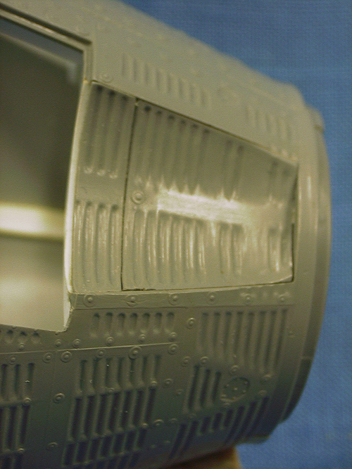
In the kit, the details of the forward part of the cabin section are poorly represented. This includes the Reentry Control Section (RCS Section) and the Rendezvous and Recovery Section (R&R Section), parts 15,16 (Capsule Forward Section, right and left half respectively) and part 17 (Nose Section). I chose some rather radical surgery to replicate the exposed channels on either side of the rectangular washers on these sections. I decided to remove and replace the washers completely and create new channels. For the RCS Section, the locator pins were removed, the seams cleaned up, and the two parts were glued together. Then using some .030” sheet styrene, two circular disks were made to fit inside the section. These were glued in and the area around each washer line was removed until a .125” wide gap was created. A razor saw made quick work of removing most of this material with riffer and needle files used to clean and true up the edges.
Because the average thickness of the RCS Section was .050”, I used the following combination of styrene strips to allow the new washers to flush up to the outer contour of the section. First, a .020” x .020” strip was glued even to the inside edge on each side of the gaps. This supported a .015” x .125” strip that filled the gap. After all seams were filled, .010” x .100” strip styrene was cut to length and carefully scribed to indicate each washer. These strips were then glued down the center of each channel. The bolts in the middle of each washer were the last detail added. Once again, a drop of white glue applied with the cut end of a toothpick mimicked these bolts.
After removing the nose fairing cover on part 17, a similar sequence was used to replicate these washers. Four support disks were used, the first at the lower end, the next 5/16” higher, then one at 5/8” from the bottom and the last at the top of the section. Because some of the washers don’t run straight up the R&R Section, a micro saw was used to remove the angled washers. The two extra interior disks allowed the R&R Section to be cut into two parts at the step (15/32” up from the lower edge) and to pick up the “V” shaped shingle on the TY axis. This cutting through the section was done after all channels were completed and a .010” x 1-13/32” diameter disk was inserted to create a seam at this location. All though a lot of work, this looked much better than simply scribing channels around the existing washers.
The nose fairing was reconfigured based on McDonnell photos of the Gemini B. The three rendezvous latch covers were also removed from the side of the R&R Section. These were replaced with styrene “plugs” attached to the nose cap. This allowed the entire nose cap to be painted without the need for masking as well as allowing for a 3/8″ dia. styrene tube to be inserted into the completed reentry module to be used as a handle for painting.
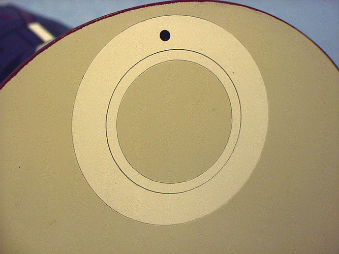
Modifications to the heat shield (Part No. 5) included removing both attachment flanges for the retro-rocket adapter, filling the prominent center sinkhole and scribing the scale 25.8” diameter heat shield hatch.
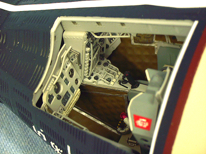
Crew Cabin – Interior Details
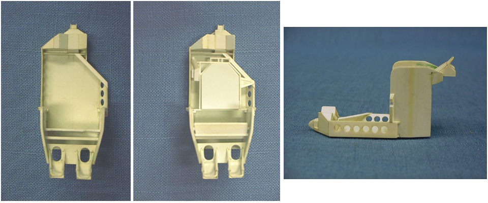
Work on detailing the interior began by removing the rear bulkhead detail and seats on part 6 (Interior Bulkhead W/Seats). The edges were filed and sanded to remain flush with the inside edge of part 4 (Crew Compartment Interior). Pieces of styrene were added to the back of part 6 to extend the crew compartment interior to the contour of the heat shield. Also a 1/8” by .040” extension was added to the back edge of part 4. The rationale for this was that I didn’t know exactly how much room in the interior the new seats and rails were going to take up and part 4 allowed for this much expansion. Because of this extension, the notches for the front instrument panel ends were cut back by about 1/16”.

Attention was now directed to the placement of the seats and seat rails. Numerous photos were scrutinized to get a sense of how the rails and seats interfaced with the hatch openings and other interior parts. I decided to use the heat shield part as the rear bulkhead; therefore the rails would have to be mounted to it. Dry-fitting the crew compartment outer shell to the heat shield and then finding the center of each hatch opening determined the rail locations. The rails needed to sit at a 12-degree angle from the Y-axis and center in the hatch opening. The width of the back of the rails was determined and two pieces of .040” x 3/8” x 2” long styrene rectangles were glued on to the rear of the heat shield. This would give the rails a positive attach point.
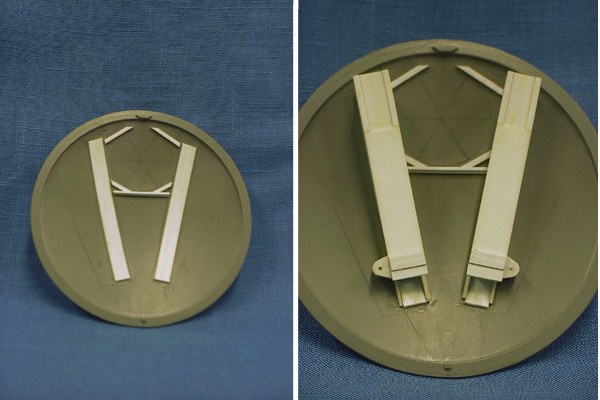
The geometry of the rails became a somewhat complicated conglomeration of plastic. Not only did the rear edges of the sides of the rails have to match the curvature of the heat shield, but when completed the upper surface had to sit parallel to the instrument panel and have a 8 degree forward angle in relation to the vehicles X axis. I also added to the outside bottom of each rail the pivot hinge for the hatch actuator pistons. At this time I scribed the LPB hatch (A scale 25” diameter hatch) into the inside of the heat shield part. Both the inside and outside hatches were scribed using a compass with two metal points.
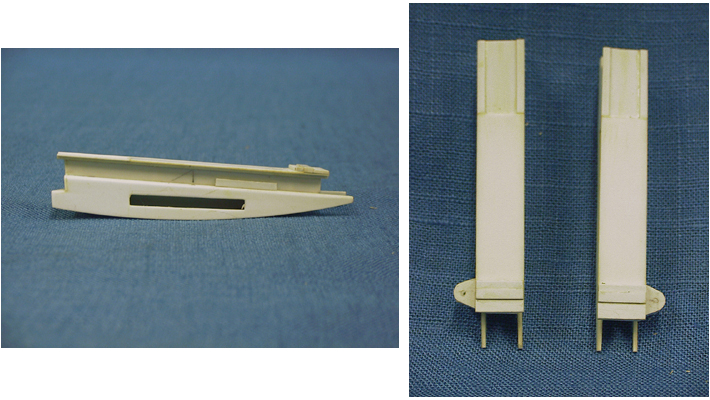
The seats were based on drawings of both the Gemini and Gemini B spacecraft interiors, several basic dimensions taken from the kit seats, and a three-view drawing that I did. Both seats (as well as the rails) were built at the same time with the commander’s seat being the “pathfinder”. Every effort was made to make the pair of seats as identical as possible. After the basic shapes were built, the cushions and ejector handle details were fabricated.
Next came the hatches, first the hinge pins were removed and a miniature piano hinge was employed to open and close the hatches. The major hatch modifications started by removing all of the molded detail from the inside surface. The recesses for the hatch sills were, in part, filled in with .030” x .030” strip styrene to match the smaller sills. The reason for reducing the width of the sills was to allow the hatch actuator piston hinge spars to sit as far back on the hatches as possible, as well as to allow the seats to slide in to the cabin during final assembly. The forward and rear hatch web spars were built in two sets of opposite pairs. These structures were fabricated from .020” stock with .010” strips for the stiffing spars. Special attention was devoted to the rear web spars so they wouldn’t interfere with the tops of the seat rails when the hatches were closed. The box-like structure that spans the two web spars was created out of .015” and .020” stock.

The hatch details were pulled from the “spares” box. The latches were HO scale diesel parts from Detail Associates Lift Ring Switcher (LR 1105), while the linkages were MU Air Hoses (MU 1508). After these parts were painted they were attached with Aleen’s Tacky Glue. I use this product quite a lot in the final assembly of smaller, non-load bearing parts. The window frames were created out of .015” and .040” sheet styrene with Grantline # 5098 bolts attached to the insides. The windows themselves were .005” clear acetate dipped in Future floor wax. Again, Aleen’s was used to attach these parts.
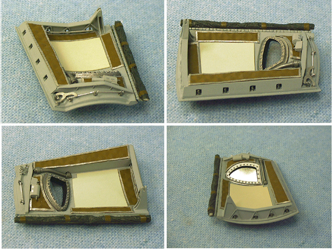
After the rails, seats and hatches were basically completed and all fit adjustments were dealt with, attention shifted to the other details within the crew compartment. The center-line beam (Part 10, Upper Interior) was replaced. On this new part as well as on the rear bulkhead (Part 6), the latch receptacles were drilled out and filed to shape. Two beams were created at the forward portion of the cabin with latch receptacles also drilled and filed. These parts took some doing. The top profile needs to fit under the coves and the instrument panels sit in front of them. Several templates were created out of thin styrene stock to find the correct shape before the actual pieces were made.
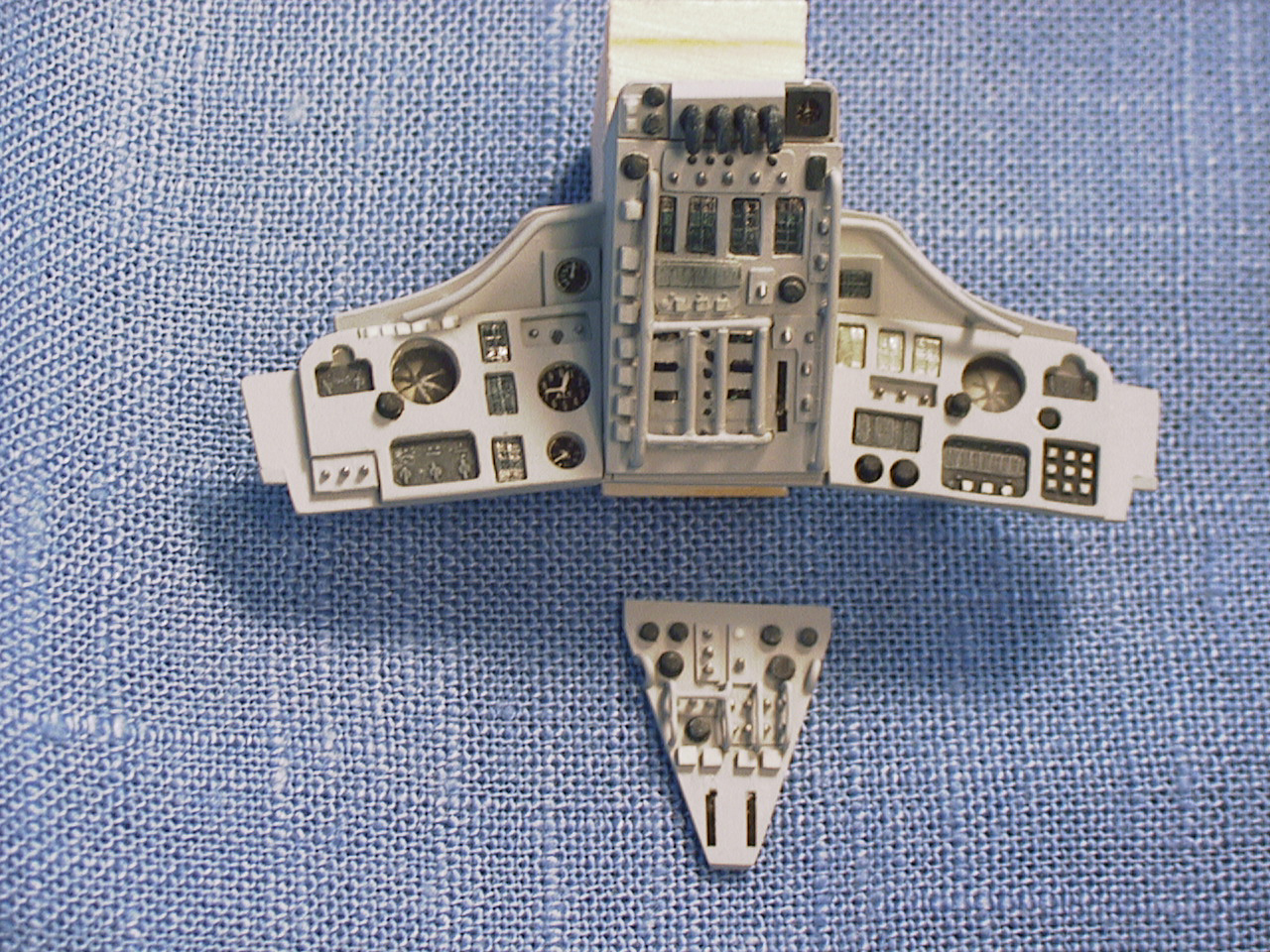
The kit instrument panel (Part 11) was also replaced with several different structures. The new instrument panel consisted of a main console (center), command pilot and pilot’s panels and the lower console (to replace Part 3). Three other circuit breaker panels also needed to be fabricated. These were located on the upper center-line beam (Overhead switch/circuit-breaker panel), and the left and right hand sides of the crew compartment interior (Left and right switch/circuit-breaker panel). The basic dimensions of the four main panels were based on the kit parts. First, backing pieces were cutout, then the actual panels were cut to their respective shapes to be placed on the backing.
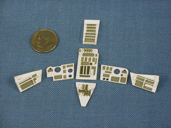
Although the relative placement of the panels was the same on both the NASA Gemini and the Gemini B, the configuration of instruments and switches, especially on the four main panels was different between the two. I used as much of the surface detail of the kit instrument parts as possible. This started with sanding the back of the kit parts down to an approximate thickness of .005” and the individual components were then removed and glued onto the new panels. All dialed gauges were taken from various Waldron Instrument placards. The two prominent Attitude Director Indicators (commonly called the “eight-ball”) were created out of the swivel stand pieces (Parts 36 and 159) from the 1/48 scale Mercury and Gemini kit. These parts have raised lines on them, and when painted, have the desired three-dimensional look.
Another change on the Gemini B vehicle was that the commander and pilot’s panels have most of their switches and instruments recessed. I assume this configuration was used to protect those instruments during the transfer of the crews into the laboratory through the LPB and heat shield hatches. Because of the recesses, the construction of these panels included a much thicker top panel that what the NASA Gemini had. All switch guards were made out of .020” styrene rod. The guards were located mainly on the switch/circuit breaker panels as well as on the main console.
Various items located on the sidewalls were also scratch-built. These included the secondary Oxygen Regulators, waste storage containers and miscellaneous storage compartments. The fabric-covered containers were made out of A & B Epoxy Putty and sculpted into the appropriate shapes. The final interior parts were the quilted blankets. The seal from a yogurt container was used. This thin aluminum had an embossed diamond pattern that was almost to scale. A paper pattern was created for each piece, the pieces were then cut out and painted and the edges were covered with thin strips of paper.
Crew Cabin – Final Assembly
Final assembly began by attaching the crew compartment interior (Part 4) to the rear bulkhead (Part 6) and fairing in that seam. The reworked center-line beam and the instrument backing panels were attached as well as the pedestal backing and its supporting structure. The side panels for the pedestal were created out of .010” sheet stock. Painting began by airbrushing the interior, including the instrument panel and hatch interiors, with Testors Light Ghost Gray. The seat frames were painted Medium Gray and the cushions Camouflage Gray. The quilted blankets were painted Field Drab with the “tape” edges painted with Testors Metalizer Non-Buffing Aluminum. After detailing, the instrument panels and most of the other interior details were installed. After attaching the LPB hatch latching mechanism (Cal-Scale Freight Air Hoses #190-276 were used for the linkages) and the seat rails, the rear bulkhead/crew compartment interior assembly was attached to the heat shield.
The RCS and R&R sections were attached to the outer crew compartment section. (Note that the RCS section needs to be rotated so that the double row of shingles is in the TY position.) There’s a bit of miss-match in diameters between the top of the crew compartment and the RCS section. This was fixed by gluing a .010” by .060” styrene strip at the lower edge of the RCS section. Now the interior and exterior assemblies were glued together. The heat shield was slightly larger in diameter in some areas and needed to be filed and sanded down to fair it up with the bottom edge of the crew compartment. Three new strap/umbilical fairings were made and then attached in the proper location to match with the adapter fairing housings. The seam between the heat shield and the crew compartment was hidden by strips of .010” x .060” styrene that had their forward edge rounded off. These were applied between the umbilical fairings and flush to the back edge of the heat shield. These strips not only hid the seam but represent the fiberite edge ring around the heat shield.
After masking the hatch openings, the process of painting the exterior began. The heat shield was painted first, with the main surface was covered with Testors Camouflage Gray and the hatch area Flat White. For the shingles on the main body, a mixture of Gloss Black and Ford Engine Blue (about three parts black to one part blue) was used. After masking, the fiberite edge ring and strap fairings were painted with Floquil British Crimson.
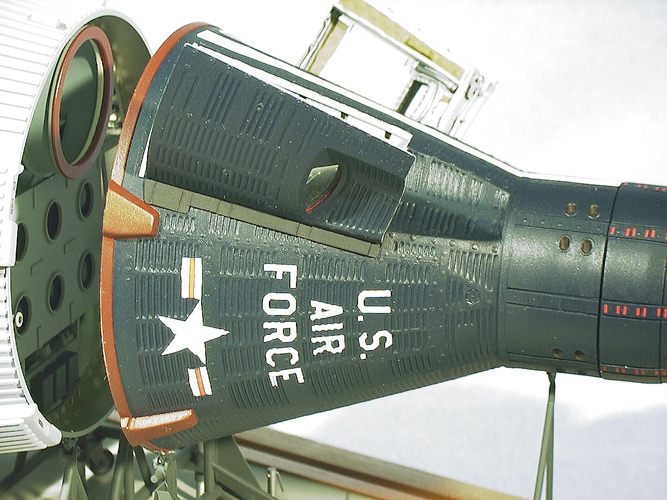
The decals were taken from Scale-Master USAF Lettering, sheet #2, SM-32B, while the insignias were from the Mircoscale 72-0084, Current US Navy Insignia sheet. I used the 1/72, 20” lettering and the 30” insignia. Each letter was individually cut out with all carrier film removed and then placed on the model. Even though a lot of work, this helped tremendously in allowing the letters to conform to the shingles. The same technique was used for the insignias, with the blue field cut away.
Fabricating the oxygen hoses and restraint harnesses finished the seats. The hoses were made out of tension springs filled with an annealed wire insert with connectors from Williams Bros. Ho Scale Pipeline and Fittings kit, No. 620. The harnesses were cut from paper, painted and Waldron 1/24th Scale Standard Seat Belt Buckles and Detail Master Racing Harness-Lever type, DM 2260 parts were used for the hardware. After all of the painting and decaling of the crew cabin was finished, the few crew cabin internal details that were not installed before were now attached. This included the seats, the left and right switch/circuit-breaker panels and the hatches.
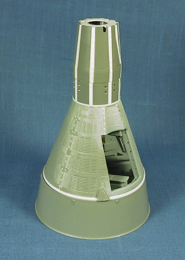
Gemini B Adapter – General
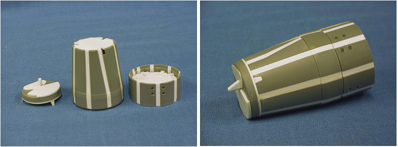
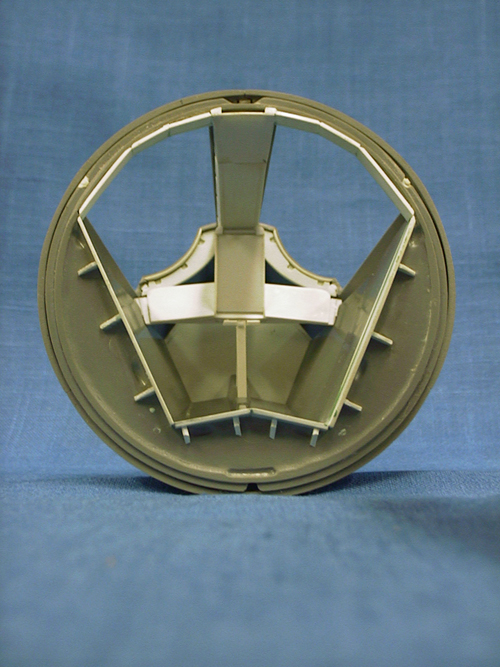
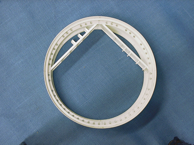
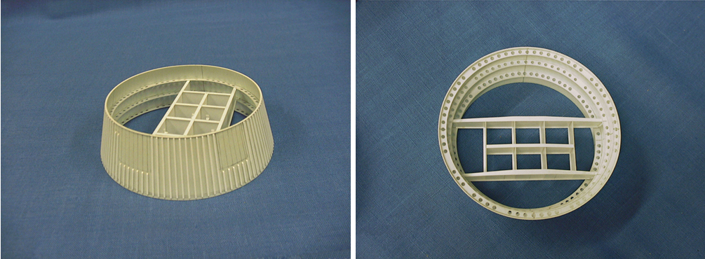
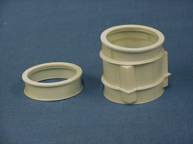
As the Gemini B adapter was so different from the kit adapter module, a completely new piece was necessary. A wooden master was turned on a lathe and the new adapter was vacuformed. The entire adapter was pulled in one piece. (The resulting shape looked a lot like a margarine tub.) The first step in transforming this into an acceptable adapter was to cut the shape to length, making sure that the top and bottom edges remained parallel. Both inner and outer surfaces were sanded with wet and dry paper, starting at 340 grit all the way down to 1,000 grit used for the final sanding. Based on a McDonnell Gemini-B Adapter shell drawing, the location of the six interior ring frames was determined and then drawn onto the inside of the adapter. Using a pair of inside calipers, the outer dimension of each ring was then established. A drawing was then generated for each frame using the dimensions taken from the adapter. The width of each frame was determined, drawn, and for rings with lightening holes, their locations were also drawn. The ring frames were cut out of .015” stock while the lightening holes were created with the Waldron Punch and Die set using the .089” size punch. The inside edge of each ring was stiffened with .010” x .030” strip styrene. The frames there then glued into the adapter with Testors liquid cement.
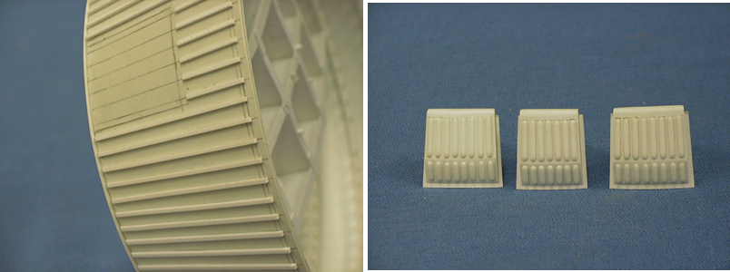
Next, the spacing for the 104 external hat section stringers was tackled. Yet another drawing was created that laid out the stringer locations as well as the 26 attachment lugs/shields on the aft end of the adapter. After this information was transferred to the adapter shell, the size and location of the three adapter fairings could be established. At this time the separation plane line between adapter sections was also located and drawn onto the adapter shell.
The adapter was then carefully cut into two sections using a razor saw and a strip of masking tape to guide the cut. The stringers were created out of .030” x .040” strip styrene. The forward edges were beveled to a 50-degree angle while the rear ends were squared off. At first I was going to use the lug shields of the Gemini adapter, but these proved to be too small to fair into the rear ends of the stringers, so the fairings were created out of .080” diameter styrene tubing from Contrail Model Aircraft.
The final two adapter ring frames, located at the outer ends of each adapter section, were dealt with in two different manners. The front edge of the retro section had a .010” x.015” styrene strip glued on edge to the outside of the shell, flush to the top, while the aft ring of the equipment section was cut from .15” sheet stock with the 26 lugs carefully carved out around the outside of the ring.
Gemini B Adapter – Retro Section
The retro section adapter fairings were constructed out of an extra adapter with enough material laminated together to create .120” thick pieces. These were shaped to fit within the three open areas between stringers and a .010” sheet-backing piece was applied. The stiffening ribs on the fairings came from .060” half round.
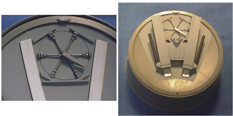
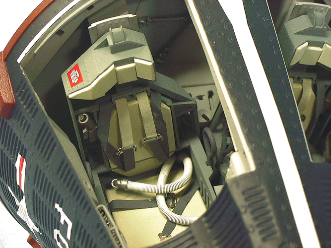
The equipment contained within the adapter sections was mainly scratch built except for the retro-rockets and the environmental cooling unit (ECU). Several modifications were made to the retro-rockets. First, the outer edge of the nozzles (Parts 26) was thinned and the nozzle lengthened by drilling out the bottom. The locator tab on the casings (Parts 24, 25) was removed and attachment rings were inserted. Two holes were drilled into the ring of the casings that surrounds the nozzle to accept the igniters (Detail Associates, HO scale, “Motorola” Firecracker Radio Antenna RA 1805).
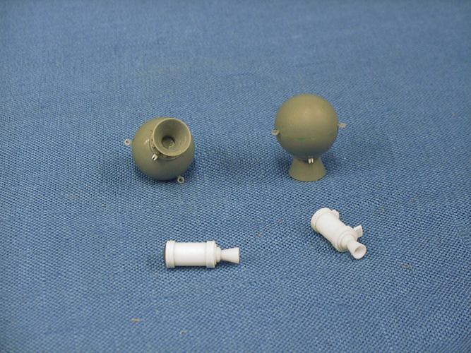
Completed retro rockets and the pad abort control system separation rockets.The ECU was also modified from the Gemini kit. All three parts (31, 32, 33) were used, but each was modified and several smaller sub-assemblies were added.
The retro-rocket support structure was constructed out of .015” sheet styrene. Both the front and back edges were stiffened with .010” x .080” strip stock. The backing panel was cut out of .010” sheet with .010” x.080” stiffeners. The mounting brackets for the retro-rockets were cut out of .015” x .030” strip for the base and .10” x .040” for the uprights. This was cut to length to make two brackets for each retro-rocket and a .025” hole was drilled in the upright to accept the mounting pins. A jig was created to position the brackets so the retro-rocket casings could be tilted to their appropriate angles.

The final major component for the retro section was the crew transfer tunnel. The cylinder for this was vacuum-formed out of .040” sheet stock from a master turned to a scale 31” diameter. The heat shield hatch cavity was built out of two adjacent sides of .250” x .375” rectangular tube placed on either side of the main tunnel cylinder. The various external stiffening rings were cut out of .015” sheet stock, while the flexible seal ends were taken from .040” sheet. The lower edge of each ring frame was covered with .015” x .020” strip. I elected to attach the tunnel only to the top spar of the retro-rocket support structure.This made installation of the tunnel much easier.
Gemini B Adapter – Equipment Section
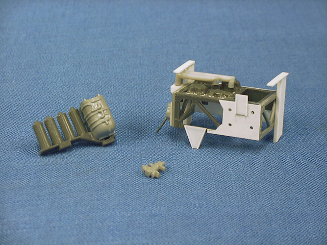
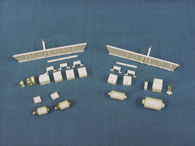
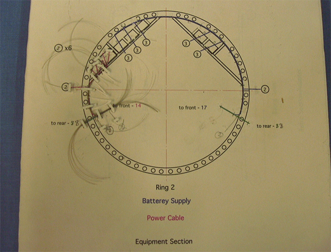
For the equipment section, the separation rockets were based on a McDonnell Gemini B interior profile drawing. The equipment support beams were constructed out of .015” styrene sheet stiffened by .015” x 3/32” strip with .060” channel used for equipment placement. The .060” channel was also used for the pick-up trusses. One side of this channel was removed to create these “L” shaped supports. The batteries were made out of .250” x .375” rectangular tube, as were portions of the encoder and guidance interface adapter while the multiplexer was created out of .187” x .312” rectangular tube. The tape memory unit was cut out of part 49 (Electronic Equipment Package) from the Gemini kit. The wiring harness connectors for all of these “boxes” were .040 styrene rod topped with Grantline 2-1/4” Nut, 5” Malleable Washers (No. 5093). The primary oxygen subsystem tanks were 1/4” diameter tube with parts 156 and 157 (Pressure Cell Half) from the 1/48 Mercury/Gemini kit used for the hemispherical ends. The cooling water tanks were created out of 7/16” diameter tube for the larger tank and 5/16” diameter tube for the smaller. The elliptical ends were filed out of .120” styrene plugs. I originally thought that the “fins” could be applied with .010” x .020” strip glued on edge to the tanks. This proved to be a mistake, so .010” sheet was used to make oversized disks (17/32” dia. and 13.32” dia. respectively). The tanks were sectioned and nine disks were glued into each tank. When these were dry, the “fins” were sanded down to a diameter just greater than the tanks.
Wiring Harnesses
The four wiring harnesses were created using a “breadboard” for each harness. The breadboards were created from the adapter equipment layout drawings with the location and number of wires needed added to the drawings. “Styrene gates” were attached to the breadboard to constrain the wires and allow portions of the bundle to breakout were necessary. Size “O” Gudebrod Bros. Silk “C” Thru Color Blending Nylon Thread was used for the wire. After all of the wires were threaded into the breadboard, the bundles were tied and paper bands glued on to allow the bundles to be attached to the adapters. The wire bundles were brush painted with thinned Testors Neutral Gray and accented with a dark gray wash. The wiring harness guillotines were made out of .125” x .015” strips with 3/64” rod.
The painting of the adapters and equipment began with the interior. A two-to-one mix of Testors Metalizer Non-Buffing Aluminum to Brass was used to paint the interior surfaces including the ring frames. Interior masking included an extra heat shield for the retro section and a disk cut for the equipment section. These were attached using a liquid masking agent while the wider ends of both sections were taped to wooden bases. The exterior was painted Dark Ghost Gray, as were the adapter fairings. A semi-gloss coat of Floquil Clear was then mixed and applied. The retro support, equipment beams, ECU frame and crew transfer tunnel were all painted Testors Medium Gray. The Oxygen tanks, water tanks, and the retro-rockets were painted Testors Non-Specular Sea Blue while the batteries were Testors European I Dark Green.

Handling Fixtures
The last elements constructed were the handling fixtures, mainly because the final dimensions of the fixtures would be determined by the finished size of the crew cabin and adapter. The first step was to figure out from the photos what these things looked like and then create a drawing for each one. The base frames of each fixture were created out of 1/8” diameter styrene tube stiffened with .062” music wire while the uprights were 3/32” diameter tube stiffened with .032” music wire. The caster support plates were .030” thick stock cut into 3/8” x 9/16” rectangles supported by .020” stiffeners.
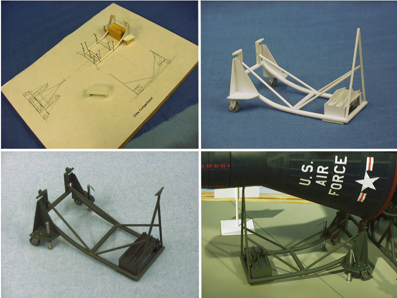
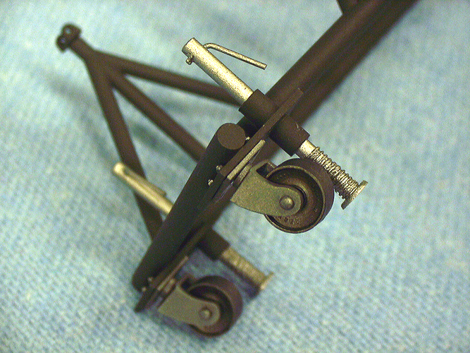
The casters turned out to be one the hardest elements to find/create. I spent quite a bit of time looking for a ready made product but could not come up with anything. Then, I ran across Grantline’s Griffin Denver 26” Dummy Wheel Sets. With a little modification these worked out to be exactly right for the fixtures. Gluing two of these wheels together, face to face, and then sanding off the center ridge created an appropriately sized wheel. The axle was .060” styrene rod, while the yokes were made out of .187” x .312” rectangular tube. The upper plates were pieces of .020” thick styrene sheet cut into 1/4” squares with a .040” thick, .120” diameter plug between the yoke and plate. The fixtures were painted with Testors European I Gray while the casters were painted with Testors Metalizer Titanium.
The final assembly consisted of a creating a drawing showing a plan view of all of the fixtures and their relative spacing. This was placed on the sheet styrene base and with a pin vice, holes were drilled under the caster locations to accept a .010” thick piece of music wire which attached the castors to the base. The finished modules were then attached to the fixtures and the fixtures attached to the base.
As mentioned throughout the article, quite a few drawings were perused and created of the assemblies that went into this model. These drawings supplied dimensions and allowed me to check clearances. Without these, I never would have been able to achieve a consistent level of detail and alignment.


