
NASA’s Saturn IB in 1:48 Scale
Part One –
A brief history and Vehicle Description
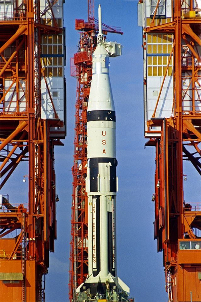
The uprated Saturn I (also called the Saturn IB) was the second of three launch vehicles developed to implement the primary goal of Project Apollo, “to put a man on the moon and return him safely to the earth”. By uprating the first stage of the Saturn I and replacing the Saturn I’s S-IV second stage with the S-IVB stage being developed as the third stage of the Saturn V, a launch vehicle with a payload capability of 35,000 Lbs. would be realized. When this launch vehicle was officially introduced to the public in July of 1963, most of the engineering work of mating the proven S-I first stage, whose development started in 1957, to the S-IVB stage had already been accomplished. This vehicle would allow NASA to test several major elements of the Apollo lunar mission on an earlier time frame than if they had waited for full development of the Saturn V. The Saturn IB also pioneered NASA’s Office of Manned Space Flight mandate for “all-up” testing; having all major launch vehicle and payload hardware functional on all flight tests. While first flown in February of 1966, the Saturn IB also had the distinction of boosting the last Apollo hardware flown with the 1975 launch of the United States’ portion of the Apollo/Soyuz Test Project (ASTP). In all, NASA successfully launched 32 out of 32 Saturn vehicles (Saturn Is, Saturn IBs and Saturn Vs) with the Saturn IB contributing nine missions to that total.
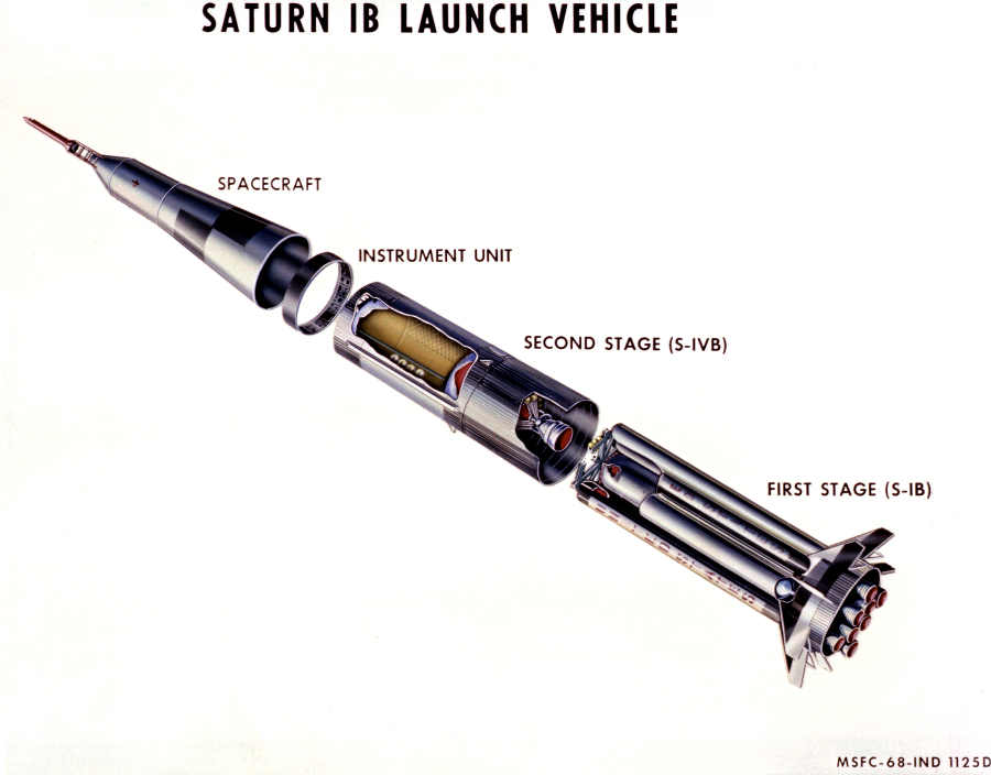
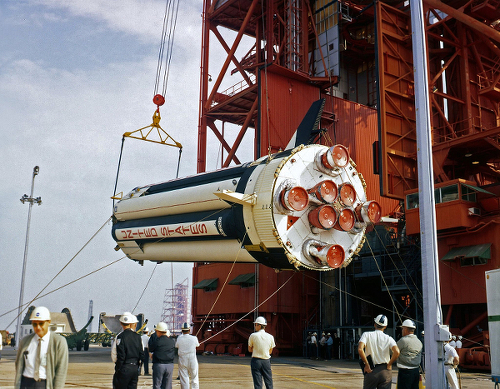
The complete Saturn IB with an Apollo payload stood approximately 224 feet tall and weighed at launch about 650 tons. The specific vehicle I choose to model represents the one used on the Apollo 7 mission, the first manned Apollo flight. This vehicle consisted of the first and second stages, the instrument unit and the Apollo spacecraft. The first stage (S-IB) included a thrust structure, nine propellant tanks, eight fin assemblies and eight H-1 engines. Manufactured by the Chrysler Corporation, this stage stood 80.3 feet tall and had a diameter of 22.8 feet (40.7 feet if one includes the fins). The center propellant tank, which carried liquid oxygen (LOX) was 105 inches in diameter and was constructed from tooling derived from the Jupiter IRBM (Intermediate Range Ballistic Missile) program while the eight 70 inch diameter outer tanks [four for LOX and four for fuel (RP-1)] used tooling from the Redstone SRBM (Short Range Ballistic Missile) program. The H-1 first stage engines were developed and manufactured by Rocketdyne, a subsidiary of North American Aviation, and were based on the engines (S-3/S-3D) developed for the Jupiter and Thor IRBM programs. For the Apollo 7 mission, each engine developed 200,000 lbs of thrust for a total first stage thrust of 1,600,000 lbs.
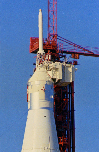
The S-IVB second stage, manufactured by the Douglas Aircraft Company, was basically identical to the third stage of the Saturn V and consisted of liquid hydrogen and oxygen propellant tanks and a single 200,000 lb thrust J-2 engine (also developed by Rocketdyne). This stage, which incorporated a common bulkhead between the two propellant tanks, was 21.7 feet in diameter and 58.4 feet in length. The Instrument Unit (IU) built by International Business Machines (IBM), was a three-foot tall, 21.7-foot diameter ring sitting atop the S-IVB stage. This contained the Astrionics system, (the vehicle guidance, control and instrumentation systems) which controlled the entire vehicle during the boosted portion of flight and while the S-IVB was in orbit. It was also nearly identical in layout and equipment to that used on the Saturn V.

The final element of this version of the Saturn IB was the Apollo payload. North American Aviation’s Space and Information Division was responsible for all elements: the Spacecraft/Lunar Module Adapter (SLA), the Command and Service Module (CSM) and the Launch Escape System (LES).
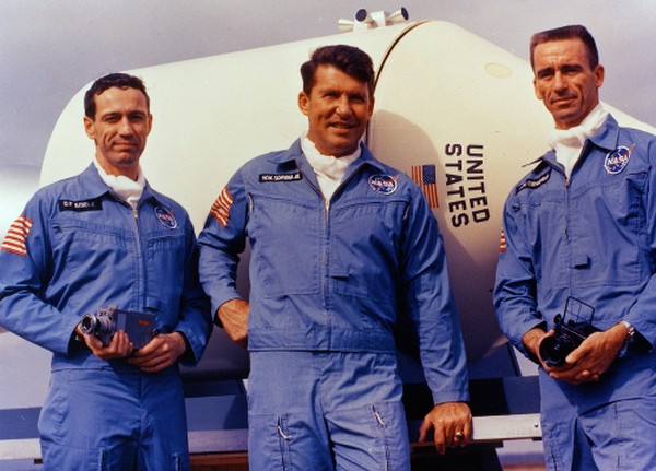
The Apollo 7 mission, AS-205 was launched on October 11, 1968 from launch complex 34 at Cape Kennedy Air Force Station, Florida and splashed down on October 22, 1968 in the Atlantic Ocean. This mission was the first manned Apollo flight, which was an 11-day Earth Orbital test designed to check out the redesigned Block-II CSM. Commanded by Walter M. Schirra with senior pilot/navigator Donn F. Eisele and pilot/Systems engineer R. Walter Cunningham the flight was considered a complete technical success, which contributed to NASA’s decision to man the third Saturn V flight and launch it into lunar orbit two months later (Apollo 8).
The Model – Fabrication
I’ve always felt that the Saturn IB was the most ascetically pleasing of NASA’s manned launch vehicles and the building of a 1/48 scale model of this vehicle had been a dream of mine for over 20 years. I started active research on the vehicle in the mid ‘80s and by the early 90’s I had enough information to draw up a preliminary set of plans. Soon thereafter I started turning the wooden masters from which the basic cylindrical and conical shapes of the vehicle would be vacuuformed. I used .040” thick styrene sheet for these initial pulls. As the 90’s progressed I would add to my inventory of pulled Saturn IB parts (especially first stage propellant tanks) and continued with my research as other modeling projects occupied my time. In 2003 I started construction on the Apollo spacecraft’s service module, the command module’s boost protective cover and the launch escape motor housing and skirt. Actual work on the launch vehicle began in 2006 with the assembly of the nine first stage propellant tanks.
As this would be the largest modeling project I had ever tackled, I decided to compartmentalize the construction and attempted to complete the majority of each section before moving to the next. Large detailed drawings were done for all of the major elements and smaller drawings were parted out as I progressed through the build. My primary challenges were in managing the numerous sub-assemblies and keeping the entire vehicle in “alignment”. I also incorporated several new modeling techniques during the construction process, these included reproducing the weld beads on the first stage propellant tanks, finding a workable method of reproducing many of the rivets on the vehicle and figuring out how to mask the horizontal portions of the black tracking markings across the stringers when it came time to paint.
Wooden male molds were turned on a lathe and the resultant shapes were vacuuformed. These female plastic parts created the major cylindrical and conical shapes. In the past, when I’d vacuuformed cylindrical tubes I would cut ring frames for the ends and reinforce the inside of the tube seams with “T” shaped styrene strips. For these first stage propellant tanks, I incorporated an additional step. To keep the tanks at the correct diameter throughout their length, I placed one-half of each tank in a simple jig and glued to the “tees” a solid rectangular piece of sheet styrene that ran almost their entire length. After gluing the cylinders halves together I filled the resultant seams with a “slurry” of Testors liquid cement and scrap styrene. This was heavily slathered into the seams and left to cure for several weeks before I began to work on the outside of each cylinder. I started by sanding the entire exterior of each tank with a 100 grit wet-n-dry sanding block. This got rid of the wood grain ghosting on the outside of the cylinders and faired down the seam areas. With finer and finer sandpaper grits, these surfaces become ready for the exterior details which would then be added.
Detail work on the outer propellant tanks began with the LOX and fuel vents (near their upper ends). These were created with a series of thin styrene disks punched out with a Waldron Punch and Die set and then glued to “washer type” shapes cut out of an extra vacuuformed propellant tank skin. After the proper size holes were drilled out, the vents were centered and glued on to the inside of the tank walls. The first stage propellant tank weld-lands were created using Plastruct .010” by .010” strip styrene which was glued down with Tamiya extra thin liquid cement carefully applied with a 0/001 brush. First, I drew out the locations for the lands using flexible straight edges. For the horizontal lands I taped one end of a strip at the back of the tank and gently stretched the piece around the circumference on each line and applied the glue. The verticals were cut to length based on the locations of the horizontal pieces. After the lands had set up I applied 3M Blue Painters Masking Tape around all of the strips to protect the cylinder and using a riffer file gently removed over half of the thickness of each land. After cleaning the residue off of the raised edges with the cut end of a toothpick, fine grit sanding sticks were used to gently bevel the remaining thickness. Any little gaps between the beads were then filled and sanded.

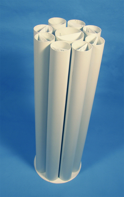
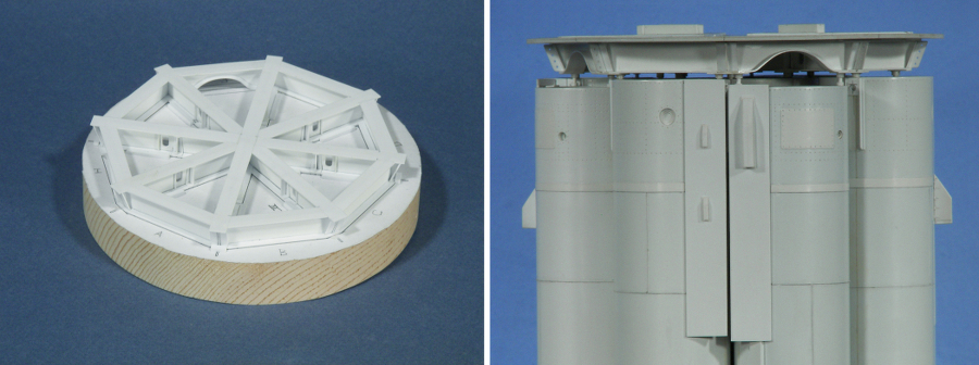
To properly set the bottom of the tanks in the thrust structure, nine .040” thick disks were cut to the inside diameter of each of the tanks and attached to a larger disk cut from .030” thick sheet. This larger disk became the upper stiffening support for the thrust structure cylinder. A similar disk was cut which would hold the H-1 engine nozzles and between these two disks, 1/8” thick styrene walls were sandwiched to further solidify the thrust structure.
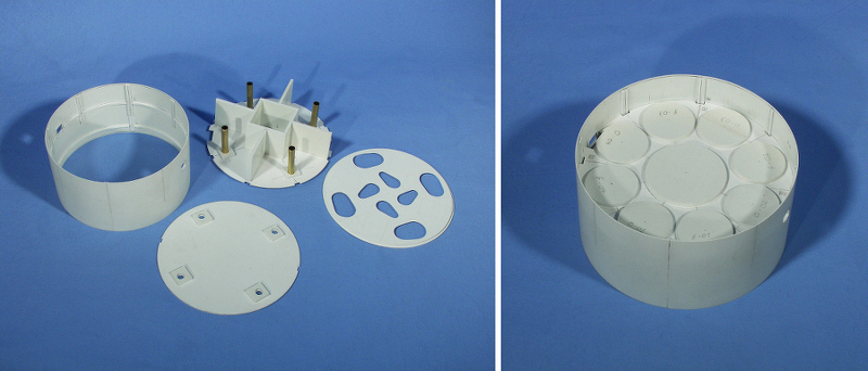
After the exterior of the thrust structure cylinder was cleaned up the external details were added. On the real vehicle, the bottom half of the thrust structure is hollow and the exterior skin consisted of sixteen alternating panels, eight being corrugated and eight smooth. Using .060” half round Evergreen strip I applied them in eight groups of fourteen strips, simulated the corrugations. On the upper half of the thrust structure other exterior details included eight personnel access panels, the openings for the two aft umbilical receptacles and location stubs for the eight fins. On the real vehicle there were many rivets on the outside of this cylinder so I chose to replicate their locations with a quick spin of a micro drill. The tedious part of this process is in the layout while the actual dimpling didn’t take that much time. However the number of rivets does add up, on the entire model I ended up replicating more than 12,500 rivets which is no where near the total on the real vehicle.
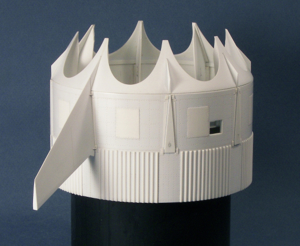
The fitting of the 60 ° fairings, which fairs in the area between the thrust structure and the outer propellant tanks, turned out to be a bit of a challenge. Originally I was gong to fit eight individual fairings, one around each outer tank. And then during the final assembly of the model attach them to the tanks and each other. However, as I couldn’t figure out a fail-safe method of accomplishing this I ended up gluing the entire fairing to the thrust structure and then cutting out the location for each of the eight exterior tanks. This allowed me to deal with any variations in fit around each tank. A paper pattern was drawn to indicate where each propellant should fit and those lines were transferred to the fairing. Using my Dremel motor tool with a small diameter drum sander, the plastic was carefully removed. Each of the openings’ final shape was refined with needle files and sand paper attached to wooden dowels.
I decided to replicate all eight first stage fins as opposed to making a master and having it cast. The sides for each fin were cut out of .015” sheet stock with the rest of the pieces cut out of .030” sheet. To keep the fins consistent, I made a .015” plastic master taken off the fin drawing to make all of the fin sides. A similar technique was used to replicate the other fin parts. The outer surface of each fin side had panel lines inscribed while the interior upper edge was beveled to remove the excess thickness.

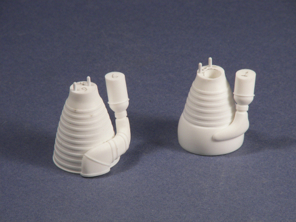
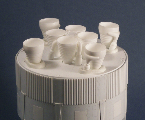
The bottom of the thrust structure was enclosed with a paneled heat shield. This was also cut out of .030” sheet stock, and after making the openings for the engines, panel lines were scribed. Two sets of masters were created for the eight engine nozzles that extend below this heat shield. The inboard engines included a sinuous turbopump exhaust duct while the outboard ones had an aspirator attached to the lower section of the nozzle. The one common piece of equipment for all of the engines was the heat exchanger itself. I made masters for these and asked Glenn Johnson of RealSpace Models to resin cast them. After I got the engine parts back from Glenn, I began the process of attaching the engines to the bottom thrust structure. The gimbaled outboard engine’s flame curtains, which kept the intense heat from the exhaust out of the thrust structure were made from Miliput Superfine two-part epoxy putty.
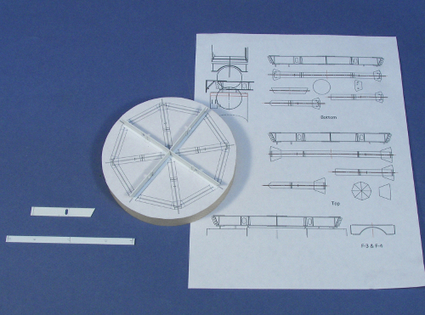
The top of the first stage propellant tanks were aligned by a structural element called a “spider beam”, similar to what was used on the actual vehicle. This assembly was also the support for the upper stage and Apollo spacecraft. I chose to replicate the majority of this transitional piece of hardware because I wasn’t sure how much of it would show when the model was done. I built up all the major “I” beam parts out of .015” strip stock and added additional detail. A plan view drawing of the finished spider beam was glued to a wooden base and a jig was created to keep all of the parts in alignment during their assembly.
Part 2 –
NASA’s Saturn IB in 1:48 Scale – Part 2NASA’s Saturn IB in 1:48 Scale – Part 2


