
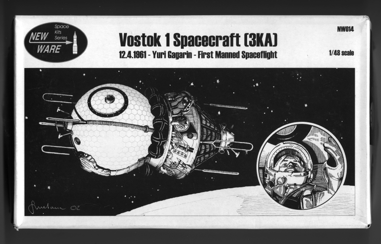
Modeling New Ware’s Vostok 1
A Brief History
In 1950, the Ministry of Armaments under the auspices of the political leadership of the Soviet Union decided to reorganize a number of the departments at the Scientific Research Institute No. 88 (NII-88). Out of this was born the new Special Design Bureau No. 1 (OKB-I) to be lead by Sergei P. Korolev. OKB-I was tasked to design a launch vehicle system capable of delivering a heavy nuclear warhead as far as the United States. The result was the “R-7” known in the west as the S-6 “Sapwood” ICBM. However Korolev, only known by the title “Chief Designer” in the west, was also as preoccupied by space travel as was Werner von Braun, who was currently working on rocket development for the U. S. Army and had just been moved to the Redstone Arsenal outside of Huntsville, Alabama. Korolev was able to convince the leadership of the Soviet Union to place the first artificial satellite, was well as the first human into orbit, which lead to the late 50’s/60’s “space race.” Variations of the launch vehicle used for these early launches, and still in use to this day are based on the Soviet Union’s R-7 ICBM.
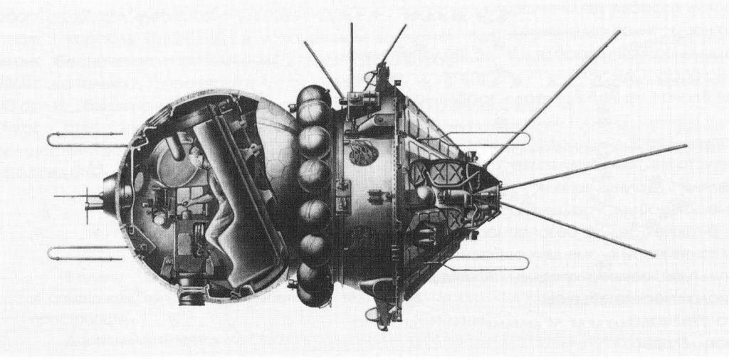
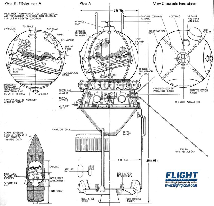
At OKB-I preliminary plans for a manned spacecraft began as early as November 1956. These were paper studies and it wasn’t until 1958 that Korolev actively began the design that became the Vostok spacecraft. In its final form the Vostok included two major sections. The descent apparatus, which was spherical in shape, contained the flight control equipment, the atmospheric gasses and the cosmonaut reclining in a 1,763 Lb. ejection seat. This sphere was 7.5 Ft. in diameter and weighed in at 5,291 Lbs. The other section was a double-coned instrument module, which was 7 Ft., 4.5 In. long and had a maximum diameter of 7.97 ft.
The descent apparatus was completely covered with a heat-resistant cover to protect it during re-entry. There were three 3ft. 3.7In. diameter hatches on the exterior of the sphere, one for the recovery parachute, one to allow for equipment access and one for ingress and the ejection seat deployment. The sphere, which had an internal volume of slightly less than 53 cubic feet, was pressurized at 14.7 PSI with 79% nitrogen to 21% oxygen atmospheric mix. The ejection seat contained its own and the cosmonaut’s personal parachutes and emergency oxygen supply. The seat could be used to eject the cosmonaut during the early phases of flight if the launch vehicle failed and was always used to eject the cosmonaut after re-entry at about a 22,965 Ft. altitude.
The instrument section, which was also pressurized, carried the equipment and instrumentation for ensuring orbital flight. One of the major systems was the TDU-1 retro-rocket, which was an Amine/Nitrous Oxide liquid propellant motor used to de-orbit the vehicle. On the exterior of the section placed just above this rocket motor were the thermal radiation louvers and at the upper end just below the descent apparatus were the 14 nitrogen compressed gas spheres used as propellant for the attitude control system.
Overall length of the Vostok in flight was 14 Ft. 5 In. (minus the antennas) and it had a mass of 10, 450 Lbs. Six preliminary test flights preceded the first manned flight. These were called Korbal-Sputnik by the Soviets. Six manned flights followed with Yuri Gagarin in Vostok-1 being the first human to “fly” into space. The Vostok design was later modified to allow multiple cosmonauts to ride. Two such missions were flown, called Voskhod-1 and Voskhod-2. The first carried three cosmonauts and the latter two. The basic Vostok design had two main uses, both as a manned spacecraft and as the Soviet’s first unmanned camera carrying spy satellite (the program was called Zenit).
Building the Kit
The 1/48 Vostok 1 (3KA) kit is by New Ware, run by Tomas Kladiva in the Czech Republic. The kit was mastered by Andi Wuestner and consists of 72 high quality pressure cast resin and 46 photo-etch parts plus decals. With the complexity of the assembly, I would consider this kit to be a real test for the less experienced modeler.
The kit instructions are well drawn and quite comprehensive with the quality of the graphics and the clarity of placement of the small detail parts well thought-out. Still, there are some part-numbering errors, so you must read through all of sheets carefully. Because of the large number and similarity of pieces, a complete study is essential to understand where all of the photo-etch and resin goes on the various modules.
The kit is broken down into major sub-assemblies with the instrument section taking up the majority of the sheets. But if you stick to the suggested assembly sequence, you might find that handling the sub-assemblies is next to impossible. I deviated quite a bit from the instructions in assembling the kit.
Construction began by sorting all the resin parts, first by where they went on the model and second by what color they were to be painted. After cleaning up the resin, the majority of the pieces were painted and the two main parts of the instrument section were epoxied together. I then located a spot where a hole could be drilled to accept the aluminum tubing, which I was going to use to support the finished model. I also drilled another hole down the spacecraft’s centerline, including the descent apparatus, for a piece of 1/8” diameter aluminum rod to re-enforce the entire model once it was assembled on the stand.
After the instrument section halves were epoxied together, The descent apparatus was temporarily glued in place. Then using Zap-A-Gap cyanoacrylate glue, I attached the four descent apparatus retaining straps plus the cap at the top of the sphere. Next, four holes were drilled for the ‘paperclip antennas’ and two for the whip antennas at the top of the sphere. The two major assemblies were disassembled and the instrument section was made ready for parts application.
With both of the instrument section cones glued together, the section could now rest on either its ‘top’ or ‘bottom’ depending on to which cone I was attaching parts. The first things applied to the section were the various wire bundles. These were the only parts that needed major attention to get a complete “wiring harness” look. Quite a bit of softening of the long bundles to bend around the angles of the module and filling of their ends to look like complete cable runs was necessary. I’d suggest that the cable runs be replaced with fine solder or styrene rod if building ‘out-of-the-box’ is not important to you. After removing the instrument sections’ photo etched parts from the fret, I used a Hold and Fold PE Workstation from The Small Shop Company to bend them into shape. Since I chose to use Testors Metalizer Non-Buffing Aluminum on most of the PE parts, I painted them after all of the bending was completed. The application sequence was to attach most of the instrument section details with the exception of the Nitrogen tanks and a couple of photo-etched panels on the sides. All of the small photo-etched ‘shelves’ that had resin parts attached were sub-assembled before being glued to the equipment module.
I was going to attach the radiator panels and other small parts to the instrument section with cyanoacrylate but I chicken out and ended up using Aleene’s Super Quick Dry “Tacky” Glue instead. This actually worked out rather well as this glue allowed me a little time to position the parts and any amounts of visible glue was easily cleaned up with water. Another plus is that sofar none of these have fallen off even though the model has traveled to many contests! The final parts attached to the instrument section were the four antennas that have their ends buried within the radiators, which were the only kit-supplied antennas used.
A suitable wooden parts holder was created to hold the Nitrogen spheres so that they could be prepped for the attachment of the photo-etch straps. There were a few pinholes that needed to be filled and then the spheres were painted with a custom dark green paint mix. After the white decal strips were applied and some Micro-Sol was used to snuggle them down, the photo-etched straps were super-glued in place.
After touching up the paint, mainly on the wiring bundles and fixing the equipment module to the stand, final assembly commenced. First, the completed Nitrogen spheres were attached and then the descent apparatus epoxied in place. The umbilical between the two sections came next and after applying the attitude control nozzles on the instrument section, the retrograde motor housing was epoxied to its end.
The last steps involved attaching the rest of the antennas. I made these out of .015-inch diameter music wire for the whips and .025-inch for the four ‘paper clips’ on the re-entry sphere. After the wire was polished, the whips were cut to the length mentioned in the instructions. The kit supplied resin whip antennas, which mimic the ones which can be seen in the Voskhod-3 photos on the internet are in their retracted state and should not be used if one is representing the vehicle in an on-orbit configuration.
Floquil Railroad paints were mainly used for the majority of the non-metallic colors. Reefer White was about the only ‘out-of-the-bottle’ color with the rest being custom mixed to match the colors seen on the Voskhod-3 photos. Off-white was mixed to paint the re-entry sphere with the hexagonal scribing being washed with a medium gray acrylic. A gray-green mix was used on equipment module and the retrograde motor housing with the details shadowed with a dark green acrylic wash. The cabling bundles were painted a soft yellow with the same acrylic medium gray washed used to accent the individual cables. Several Testors Metalizer colors were employed to give some variation to the small details on the instrument section and retrograde motor housing.
My feeling about this kit is that it’s not for the beginning modeler as the many pieces of photo-etch can be difficult to handle and keeping from knocking them off the model as the assembly progresses can be a challenge. I however, was quite please with the final outcome. The only major mistake I made was in using telescoping Aluminum tube to support the model. The model is quite heavy and the aluminum tube failed after several years. I ended up replacing the aluminum with a piece of spring steel (and had to rebuild some of the equipment module in the process).
Images of the Completed Model


