
Project Mercury Test Shot!
Scratch-building a 1/48 Scale Little Joe Launch Vehicle
History
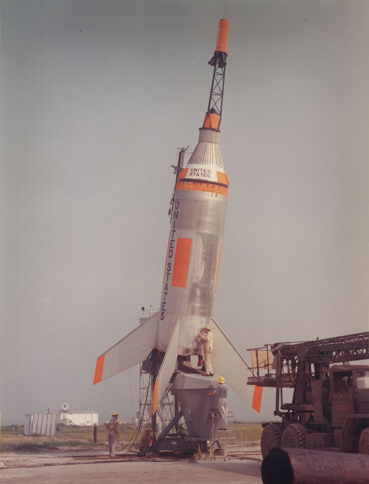
During the summer of 1958, as development and design advanced on Project Mercury, the United States’ first manned space-flight program, it became apparent that a low-cost launch vehicle would be needed to accomplish various full-scale testing associated with the launch and recovery environment of the Mercury mission. The resulting vehicle came to be called “Little Joe” after sectional drawings showed a four-hole configuration for the large solid rocket motors. This layout reminded the designers of the crap-game throw of a double deuce on the dice.
The Little Joe vehicle was one of the first boosters designed in the U.S. that utilized the concept of clustering large multiple solid rocket motors to launch payloads for research. The main solid rocket motors chosen for the Little Joe vehicle were derived from the Sergeant rocket and were called either Castor or Pollux depending on the anticipated booster flight profile. Both the Castor and Pollux motors had the same nozzle and casing dimensions and burned for the same length of time, about 35 seconds. The difference was that an individual Pollux delivered about 40,000 lbs. of thrust, while each Castor motor’s output was closer to 55,000 lbs.
As the design progressed, four Recruit solid rocket motors were added to the layout, which enhanced the operational flexibility of the vehicle. Each Recruit had about 35,000 lbs of trust and would burn for about 2-1/2 seconds. The main requirement of the booster was to qualify the Mercury spacecraft and its escape motor during the maximum dynamic portion of the Atlas launch trajectory (commonly referred to as Max q). Other test objectives of the Little Joe program included the confirmation of the Mercury capsule’s load bearing integrity during launch and abort, high altitude abort, parachute deployment after launch vehicle separation and recovery techniques after landing.
Requests for proposals to build the airframe and its associated launcher assembly were disseminated to the aerospace manufacturing community during the fall of 1958 with twelve companies responding. The Missile Division of North American Aviation won the competition and was awarded a contract on December 29, 1958 to build seven airframes and the launcher assembly. Each Little Joe could be built and launched for about $200,000.00 or about one fifth the cost of a Redstone booster launch.
The initial payloads for the Little Joe launch vehicle were pre-production mercury capsules, called boilerplates, these were designed and built at the NACA/NASA Langley Research Center. Five boilerplate capsules were used on the first five launch attempts with two McDonnell built production capsules used on the last three flights. Both of the initial boilerplate and production flights were failures with their payloads being destroyed at the end of those flights. The last two flights used the same production capsule with the last flight qualifying the MacDonnell spacecraft for manned spaceflight.
The Little Joe launch vehicle was designed with enough flexibility to accommodate several different flight regimes. This flexibility resulted from installing either two or four Castor or Pollux solids as well as the four Recruit motors. The first series of lower altitude Max q tests (LJ-1, LJ-6, LJ-1a & LJ-1b) used two live and two inert Pollux and four live Recruit motors while the three production capsule flights used two live and two inert Castor motors as well as the four Recruit motors. The one high-altitude flight (LJ-2) used the ultimate configuration, four live Castor and four Recruit motors. The process of certifying the production spacecraft and launch escape system (LJ-5, LJ-5a & LJ-5b) also included certification of the operational parachute recovery system, retrorocket package, the orbital hatch, and the spacecraft to booster umbilical fairings. Since the Little Joe was envisioned as a low-cost alternative to the Redstone and Atlas boosters, no guidance system was developed. Four large fins that surrounded the lower exterior of the booster were used to stabilize the vehicle in flight.
Flight-testing with the Little Joe began in August 21, 1959, and all of the flight tests took place from the Wallops Island Station, located on the eastern shore of Virginia. The eighth and last Little Joe flight occurred on April 28, 1961.
The Model
Digging into the program showed that all eight of the original Little Joe flights had slight differences in markings and details. So I decided to model a specific flight, finally settling on the LJ-1b round, which was the first flight to demonstrate the primary objective of the Little Joe program, a successful abort sequence while flying the anticipated Atlas Max q ascent profile. This mission was flown on January 21, 1960.
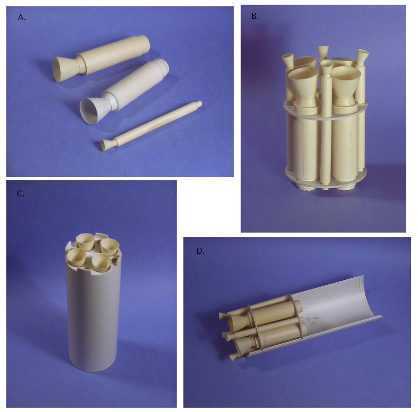
I began the model after drawing up a set of plans for the little Joe booster, payloads and the launcher assembly in 1/48 scale. Using .040” sheet styrene the cylindrical booster parts and the spacecraft adaptor were vacuuformed off of wooden masters. Sheet stock of the same thickness was used to make the disks that held the motors as well as the ring frame. The Recruit and Pollux motor shapes as well as the fins, were initially scratch-built and then multiple copies were resin cast to make up the sets needed.
After the motor support disks were fitted into the cylindrical section the two booster haves were glued together and the resulting seams filled and sanded. (See Figs.1 & 2) .005” thick sheet styrene fin-reinforcing plates were then added to the outside of the booster under the location of the four fins. After the airframe was scribed attention moved to the fins themselves as well as the adapter. The fins were mastered out of .020” styrene sheet and constructed in such a way as to allow for the inclusion of a stub wedge, which could be attached to the airframe and created a positive attachment surface for the fins to the airframe.

The two halves of the spacecraft adapter were sanded to the correct length, attached together and then the location of the twenty bolt attach cutouts were cut away near the top of the adapter. The locations of the cutouts were determined by using a paper pattern that was taken from the plans. The cutouts were backed with .010” styrene sheet stock and all voids were filled. A short lip was added to the inside of the top of the cylindrical booster and a .005” by .020” styrene ring was glued to the outside of this lip. The lip and ring centered the adapter on the launch vehicle cylinder and created a panel line between the adapter and the top of the booster.
At the bottom of the booster, a modified cruciform I-beam was created that supported the lower portions of the recruit motors and the fins on the launch pad. This was made of .010” styrene strip and sheet. The sheet was cut to the cruciform shape and the strip was used for the sides of the shape.
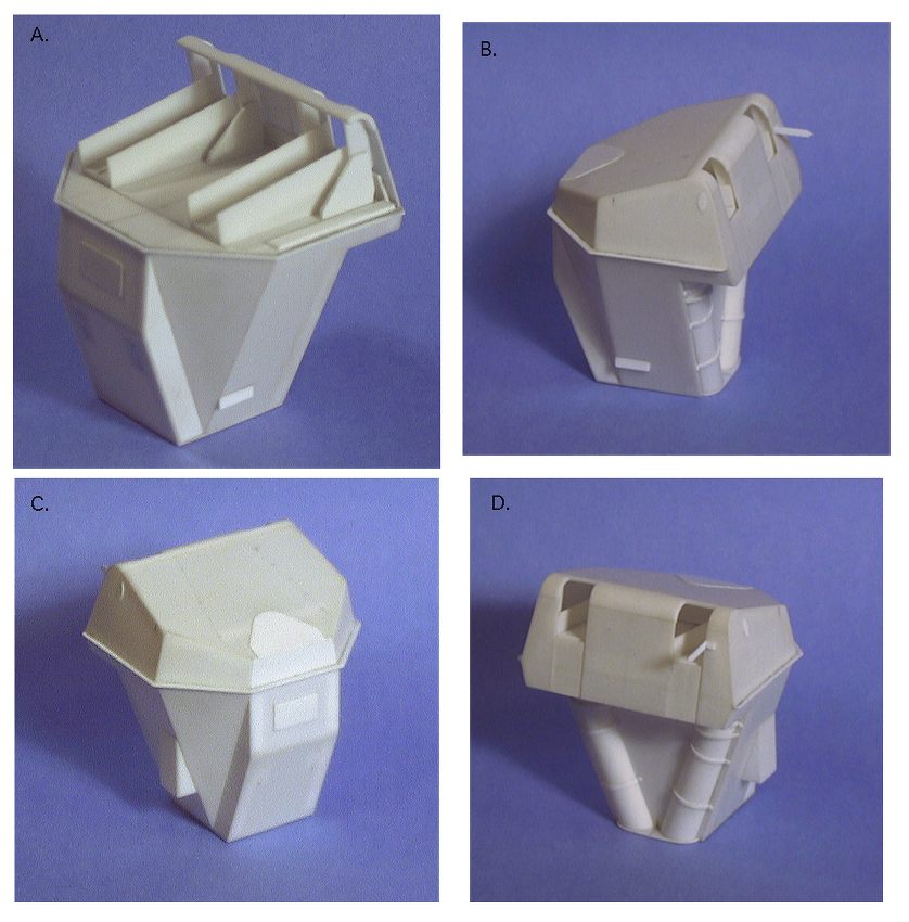
After construction on the booster was finished, work turned to the payload. The LJ-1b round utilized a Mercury boilerplate capsule shape. While the size and shape of the boilerplate was the same as the production capsule, the exterior details were completely different. For the spacecraft shape itself, I vacuuformed parts for the crew cabin section, parachute compartment and the antenna canister. The exterior details on these parts were added using strip and sheet styrene of various thicknesses. These parts were then resin cast.
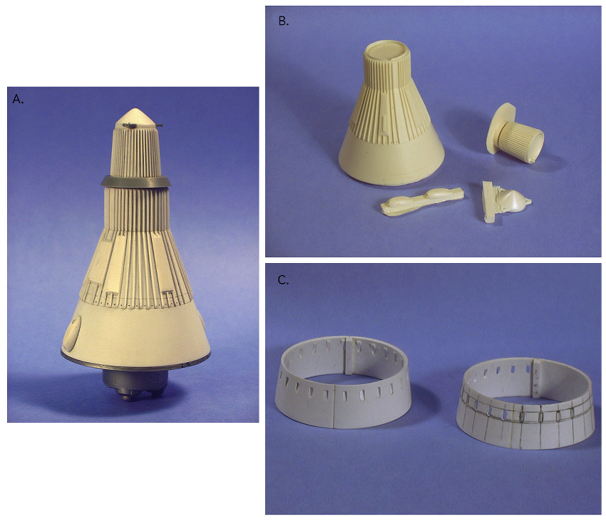
I used some of the 1/48 Revell/Monogram Mercury kit parts for the escape tower but scratch-build most of the assembly. Styrene rod was cut to make the tower legs and a jig was created that allowed the three basic parts for each tower leg to be assembled. The three tower legs were temporarily attached to the kit aero-wedge fairing and also to the modified bottom of the escape motor. The new antenna cap was then attached to each leg and .020” styrene rod was cut to fit for each horizontal and diagonal tower strut needed. The kit also supplied the main escape motor exhaust nozzles.
The Launcher
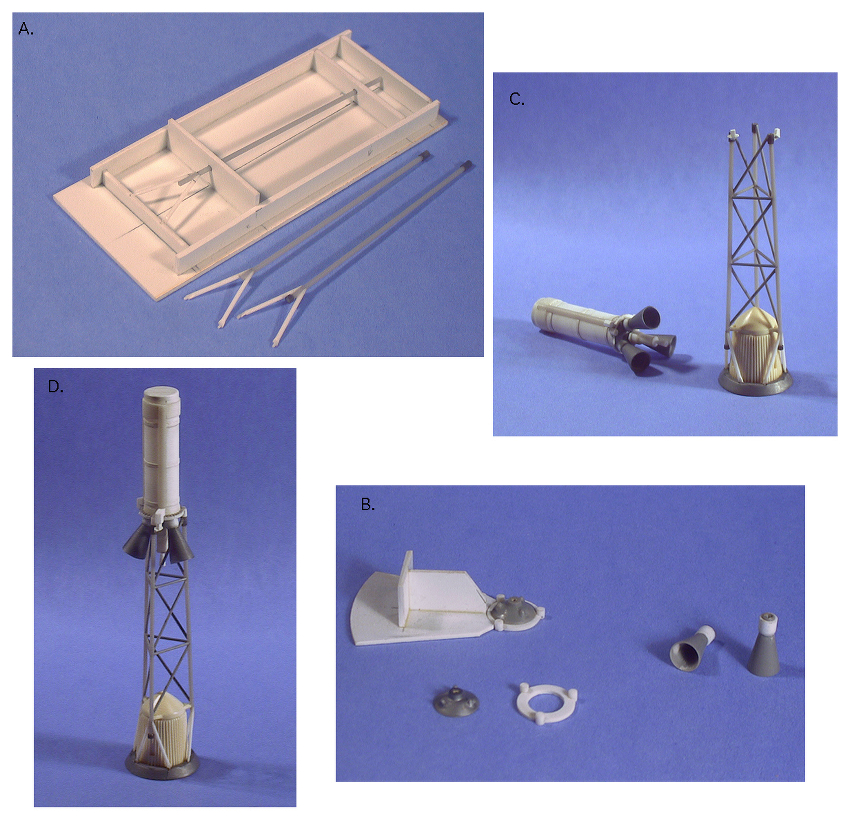
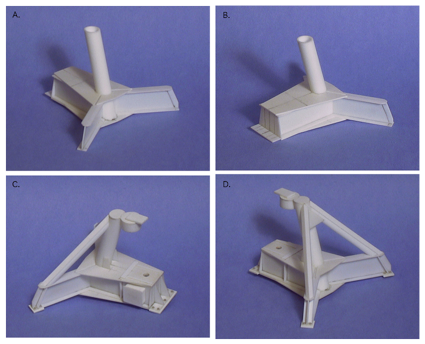
The launcher was based on photographs taken by Sven Knudsen as well as contemporary photographs and drawings supplied to me by Ben Gunther. I re-drew the launch pad and support mast based on these sources and used these drawings as well as a scaled parts breakdown to create the launcher for the model.
The launcher consisted of the base, launch vehicle support, pivot and jackscrew cover, and the umbilical mast assemblies. Because the Little Joe was unguided, the launcher was constructed to allow the vehicle to be aimed in both azimuth and elevation. Both movements were controlled by electrically powered jackscrews with limit switches that could be manually set to prevent over-travel. The elevation change was limited to 20 degrees from the vertical while the azimuth travel was limited to 90 degrees.
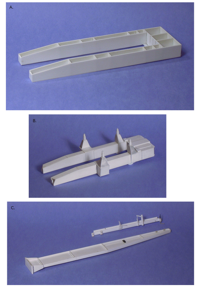
Construction started with the tripod shaped base assembly, which supported the rest of the launcher. .010″, .015″, .020″ and .030″ styrene sheet as well as Evergreen tube was used to make the base assembly. The launch vehicle support assembly was tackled next and this structure with its four launch vehicle support pads needed to fit the bottom of the Little Joe airframe. The U-shaped rectangular boxes were constructed with .040″ sides and joists and covered with .015″ skins. The mast support pads were added, as were the four booster support pylons. The jackscrew cover assembly was tackled next. This was constructed mainly out of .015″ sheet stock and included two “ramps” which allowed the legs of the support assembly to be positioned at an 80-degree elevation.
The mast assembly consisted of two I-beam sections constructed out of .015″ sheet for the web and .010″ strip for the flanges. The stabilizing arm at the top of the lower mast included a small length of piano wire to attach the top of the booster to the mast. The various lines and mechanical devices used to retract cables and such were then cobbled together.
The base for the model was made out of .040″ styrene sheet glued to a ¾” plywood sheet cut large enough so that an acrylic dust cover could cover the model. The mounting pads for the launcher were added, as were sections of the rails that supported the scaffold, which was used during the erection of the vehicle onto the launcher. An oak frame was then added to finish off the sides of the base.
A last test fit of all of the major sub-assemblies was carried out and any tweaks were performed before disassembly and the process of painting and decaling could begin.
Paint and Decals
The Little Joe launch vehicles and boilerplate capsules were finished in high-contrast colors to aid in photographic documentation of the flights. I ended up using an old Scale-Master solid color sheet that was a very close match to Testors International Orange (FS 12197) that looked to be close enough to the orange used on the Little Joe vehicle. This allowed me to use the decal sheet on the fins and the cylindrical areas of the model.
Prior to painting the launcher, the small assembly details were finished off. These included rivets made with white glue, Grantline bolts and grab handles out of some railroad detail sets I had. The sub-assemblies were then given a primer coat, any flaws were taken care of and Testors Medium Gray, FS 35237 was applied. The model base itself received a coat of Floquil Concrete and the metal rail guides were hand painted using Testors Metalizer Magnesium. Some general staining and blast effects were added using thinned paint and pastel chalks.
On the Mercury launch escape system, the tower and escape motor parts were first primed with Testors Lt. Gull Gray and then airbrushed with several light coats of Floquil Reefer White. The escape motor casing and antenna canister were then painted with the International Orange color. The tower, bottom of the escape motor including the three nozzles and the stability wedge had Testors Flat Black applied. The tower jettison motor was painted with Floquil Reefer Yellow. After all escape tower/motor parts had dried, the parts were carefully assembled using 5-minute epoxy.
The main airframe cylinder, adapter and fins were all primed with Alclad primer and then Alclad II Dull Aluminum was applied. The fins were masked leaving the leading edge exposed and Testors Metalizer Aluminum was used to give some color variation. Paper patterns were created for the orange and black markings on the fins and these were cutout from the Scale-Master solid decal sheet and applied with some Micro-Sol to help settle them down. The International Orange panels on the cylinder were also cut out of the solid decal sheet using paper patterns for size. It took two sets of decals to get the orange opaque enough on the metallic surfaces. I drew up the UNITED STATES stencils for both the airframe and capsule in my antiquated 2D-CAD program and the file was sent off to Rick Sternbach of Space Model Systems. Rick kindly created the decals on his now defunct Alps printer, which truly finished off the look of the model.
The exterior of the Castor motors were painted with Floquil Reefer White and then masked to paint the orange and yellow colored bands on the nozzles. The interiors of the nozzles were painted with a deeper shade of Alclad. A similar technique was used on the recruit motors with the exterior colors being red and Alclad II Jet Exhaust.
Final Assembly
The capsule was attached to the adapter section and the Marman Clamp cover and fairings were created and applied. After a coat of primer the entire capsule/Marman clamp fairing/adapter was painted Floquil Reefer White, then masking was applied to spray the upper half of the boilerplate Folquil Old Silver and the lower part of the adapter Alclad Dull Aluminum. The white on the capsule side and the Dull Aluminum on the adapter was then masked off with the resulting area sprayed Testors International Orange. After masking off the orange band on the adapter the Marman clamp cover/fairings were painted flat black. Paper patterns were also created for the orange panels on the capsule shape and the solid orange decal sheet once again supplied the color for those areas.
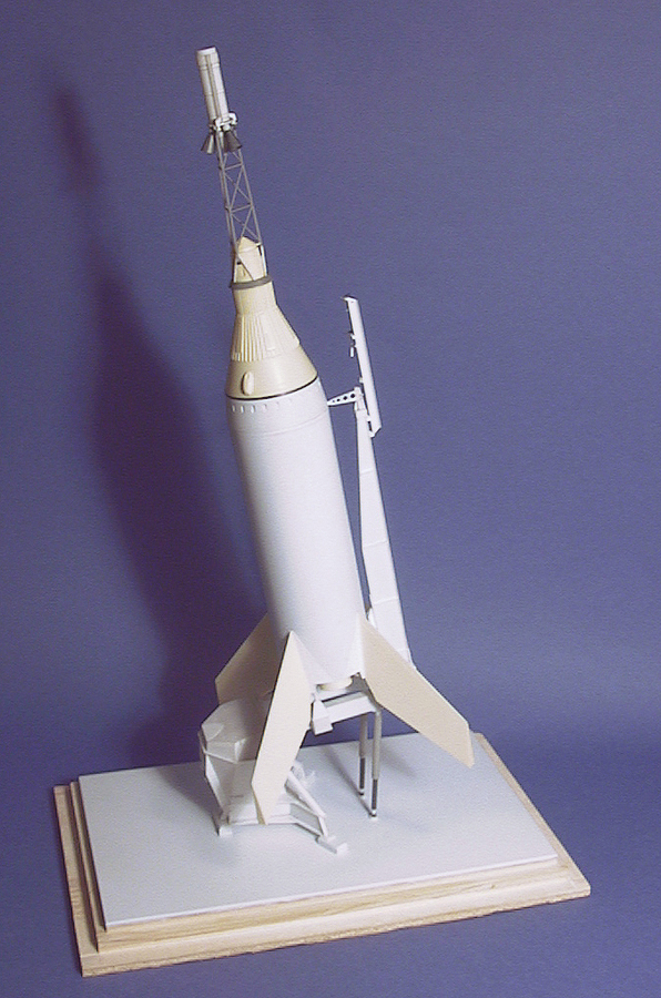
For final assembly, the launcher subassemblies were attached together using 5-minute epoxy and the launcher was attached to the base. After the motors and their cruciform support were attached to the bottom of the airframe, this was attached to the launcher. The capsule/adapter assembly was then added to the top of the airframe and the umbilical wiring added from the launcher to the rocket. Finally the escape tower assembly and the fins were attached to complete the model.
At 1/48 scale, the Little Joe is small enough to sit comfortably on the shelf yet large enough to show-off some of the details of the real thing. All of the North American Little Joe boosters were used in the test program but the launcher and two replicas are still in existence. It’s a long trip out to the Wallops Island Visitors Center, that’s where the launcher and one replica is exhibited. The other replica resides at the Hampton Air Power Park, Hampton, Virginia.
Photos of the Finished Model


