
NASA’s Saturn IB in 1:48 Scale
Part Two –

Fabrication (Cont.)
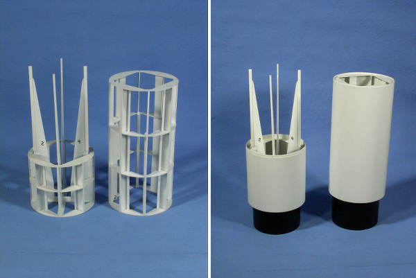
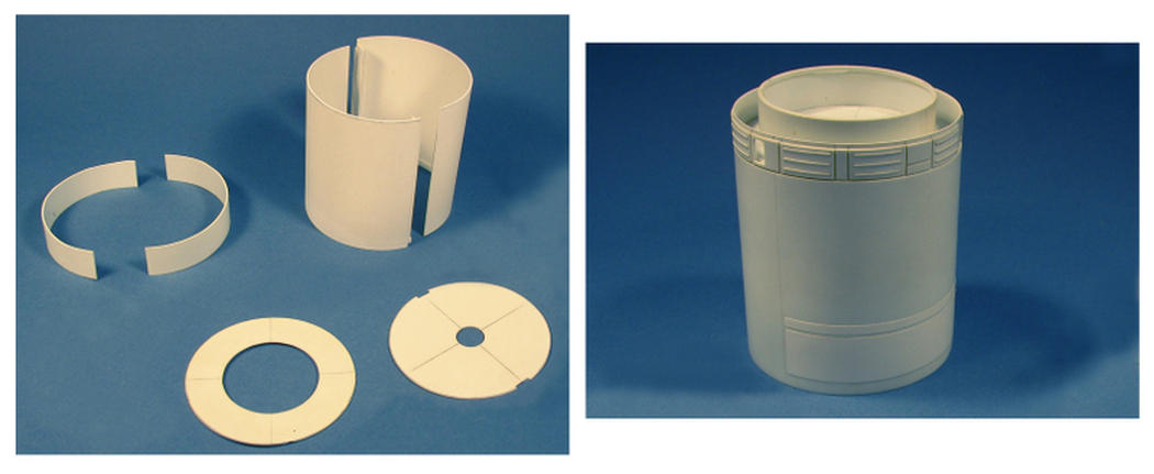
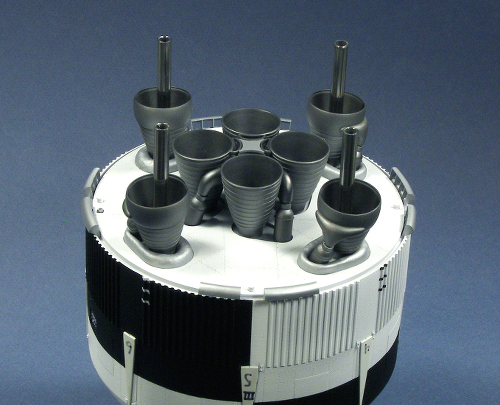
The S-IVB upper stage consisted of the Aft Interstage Aerodynamic Fairing, the Aft Interstage (which on the actual vehicle is a large hollow structure that houses the J-2 engine and its thrust structure), the S-IVB Aft Skirt, propellant tank skin and the Forward Skirt. On top of this stage was the Instrument Unit (IU). As all of these cylinders had the same diameter I ended up building two similar cage-like structures to which I could attach the cylindrical skins. I originally thought I’d split the model at the interstage-aft skirt joint for transportation purposes so I built a sliding interface connection into the inner frameworks. The exterior skins for the upper part of the vehicle were vacuuformed in two large halves. The vacuuformed pieces for this included all of the above as well as the Spacecraft Lunar Module Adapter (SLA). After attaching the skins to the frames, the exteriors were prepped using the same techniques I had used on the first stage propellant tanks.
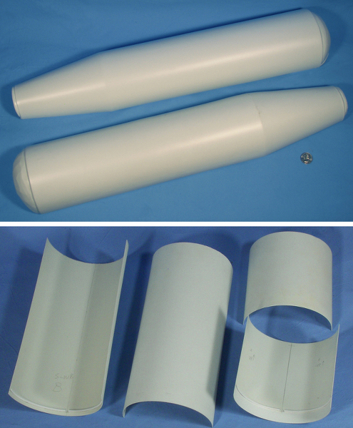
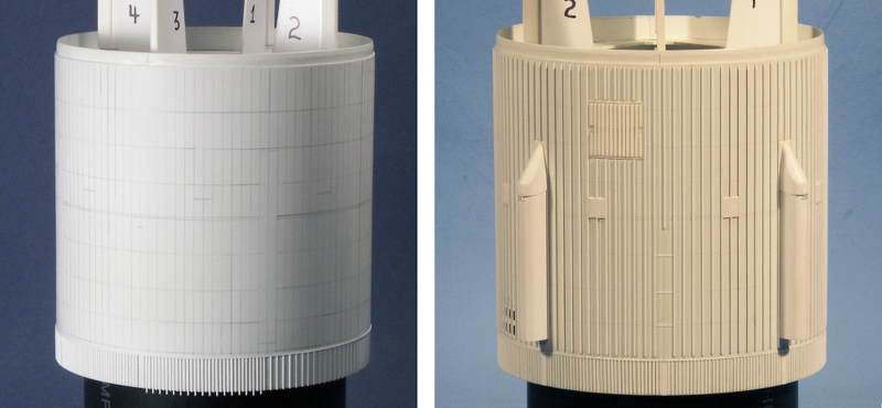
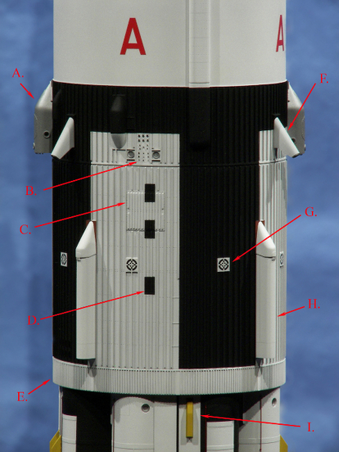
On the real vehicle, there were 112 external S-IVB interstage and aft skirt stringers, 1.375” by 1.00” in size, for the most part equally spaced around the cylinder. On the model, I chose to replicate these with 112 .030” by .020” Evergreen strips. To space the stringers I generated a plan view drawing of the cylinder with 112 equally spaced lines, sat each cylinder on this plan and ticked off the location for each stringer. Then using a long “L” shaped straight edge I penciled in their locations. Marking these points and transferring these lines introduced some error, which was expected, so to attach the stringers I made three guides. The first had the ideal width, while the other two were slightly thinner and fatter in width. To start attaching the stringers, I glued the four cardinal point stringers in place, being careful to keep these vertical on the cylinder, and then using the ideal width guide began to add the adjacent stringers. As I filled in each of the quadrants I kept a lookout for discrepancies, and when they showed up, which they did, I’d use either the smaller or larger guide to get the stringers “back in line”.
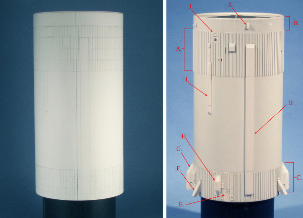
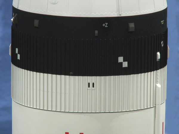
The forward skirt was similarly treated. The number of stringers was less (108) and their size smaller (I used .015” by .030” Evergreen strip) but the attachment technique was the same. On both of the skirts, the areas around the stage’s exterior umbilical connections and cable raceways covers caused the stringers to vary a little from the pattern and this was dealt with as the stringers were applied. All of the fairings, antennas and cable covers that protruded out from the second stage and instrument unit were made either from styrene sheet, vacuuformed shapes or a combination of both, After these odds and ends were created, some of these were applied to the stage prior to painting.
The conical section that makes the transition from the instrument unit to the service module (the SLA) was treated the same as all the others and after the seams had been dealt with the external detail was added. The eight prominent hinge and upper panel corner fairings were laminated from two layers of an extra SLA piece and then sanded to shape. I used my Dremel drum sander to do most of the basic shaping with finer grit sandpaper blocks to refine the edges. After the shapes were finished they were attached to the SLA. The rest of the detail on the SLA consisted of .005”, .010” and .015” strip, all of which were glued down with Tamiya Extra Thin cement. As before, the locations of all of these details were taken from my original set of drawings and were then transferred onto the cone.

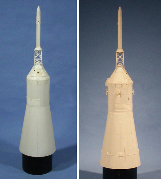
The Apollo spacecraft Service Module (SM) started out with the two .040″ thick vacuuformed halves being squared up. A circular ring and disk were cut out of sheet styrene to keep the upper and lower edges of the SM in round. The butt joints of the SM were supported with “T” shaped re-enforcing beams that ran the length of the cylinder. The upper fairing on the SM was created out of a .030″ thick cylindrical section that was set back .040” from the SM exterior and the eight electrical power system (EPS) radiators were cut out of an extra vacuuformed SM skin. The raised radiator “ribs” were cut out of .010” by .030” strip and added to each radiator. I used a strip of .0150” by .020” below and between each of the EPS radiator panels. For the two environmental control system (ECS) radiators I glued two rectangles of .005” sheet to the SM cylinder and used .030” half round for the “ribs”.
The SM RCS panels were cut out of .005” sheet and tiny “rivets” of .005″ styrene were punched and individually glued to each sheet to represent the bracket attach points for the RCS propellant tanks. I took a very fine hypodermic needle and filed the end to make the punch. The RCS quad housings were scratch-built and the 16 reaction control system (RCS) nozzles added, Glenn Johnson of RealSpace Models supplied the nozzles.
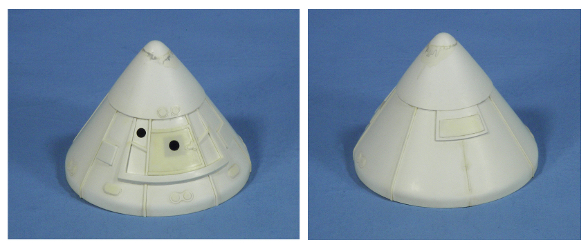
I choose not to replicate the command module as the boost protective cover (PBC) covered the entire CM. The PBC skin was vacuuformed over the original command module (CM) form with a .040″ styrene CM skin in place. The additional thickness at the apex was created with a second, thinned down PBC skin. The external details were cut out from an additional BPC skin and styrene sheet of various thicknesses.
The launch escape system (LES) rocket motor skin was also pulled off of a wooden master as was the structural skirt. The external details added included the two jettison motor nozzles, external cable conduits and on the aft skirt, the tower attachment lugs and the four launch escape motor nozzles.
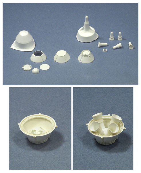
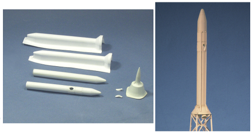
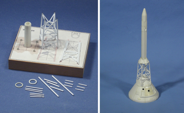
To construct the lattice-like tower for the escape system, I used Plastruct .080” and .060” rod and made a jig to build the tower sides. I made up four sets with two of them containing the outer legs. I then attached these four sets together using the upright portion of the jig to align the sides. The ring, which is included near the top of the tower was cut out of a solid chunk of .060” sheet stock and when finished, was placed in the upright jig with the pre-assembled tower around it so that the eight upper support tubes could be added. After this had dried I removed the tower from the jig and added the eight lower ring tubes.
Constant dry fitting of parts and sub-assemblies was essential as the build progressed, and after several overall dry fits I was confident in the procedures that would be necessary to do the final assembly.
Painting
The sub-assemblies were primed with a mix of Gunze’s Mr. Surfacer 1000 and Mr. Thinner. Any seam work left was taken care of by brush applications of Mr. Surfacer 500, sanding sticks and the reapplication of the primer where necessary. I used Tamiya Flat White (XF-2), Flat Black (XF-1) and Dark Green (XF-61) for the majority of the model. I was going to blue my white and take the black down a bit but I had no idea how much paint was going to be used to finish this model so I used the colors straight out of the bottles. The engines were painted with Alclad II Steel, buffed out with some SNJ polishing powder and then lightly over sprayed with Alclad II Aluminum. On the service module I used the Tamiya White and a 50/50 mix of Alclad II Dull Aluminum and White Aluminum.
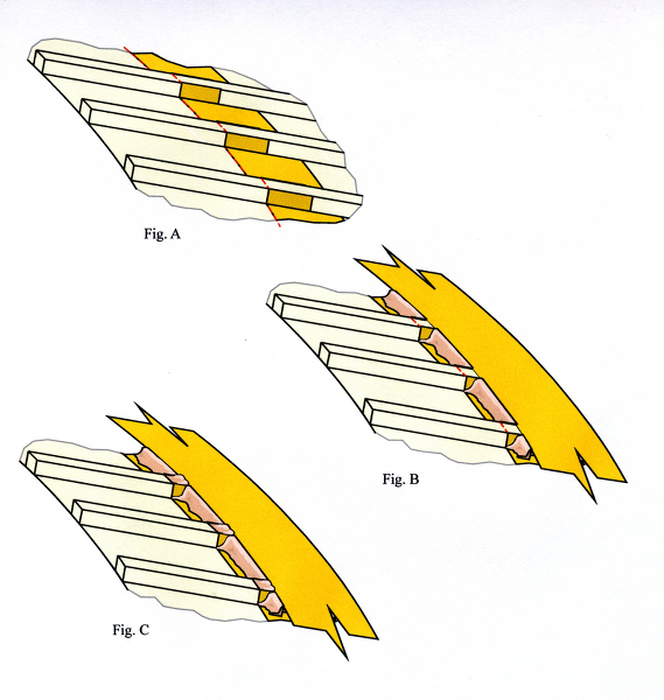
I knew that the paint masking was going to make or break this project and there was quite a bit of it to do. The most challenging involved the horizontal black and white separations that cross the stringers on the S-IVB stage. After I’d gotten the white paint to the state I wanted my first masking attempt involved cutting some intermediate lengths of Tamiya masking tape about 3/16” wide and simply laying it first on the top of a stringer, burnishing it down the side, across the cylinder face up the side of the next stringer and so forth. When I had finished applying one of these masking strips the corners between the stringers and cylinder had all pulled up just a little and I couldn’t get them to sit back down. As I couldn’t figure how I’d fill these little “holes”, even with a liquid masking agent and keep the edges straight, I knew this technique wasn’t going to work.
After a bit of musing I came up with a plan “B”. As the “valleys” between each stringer were made up of three planes, I decided to attach a separate piece of tape to each of those surfaces. This would make for a laborious application but eliminate the corner issue. I ended up cutting Tamiya masking tape to the same height as the stringers and using short segments, about 1/4 “ long, taped each stringer side. The “valleys” were filled with wider pieces cut to fit between the stringers. To complete the edge masking, I added a wider strip along the top of the stringers but set back a little from the actual separation line. I then used liquid latex as a masking agent to fill-in between the areas were there was no tape as well as to seal all the edges between tape pieces. It took over four days to do all of the masking on the S-IVB and Aft Interstage and a little over two days to paint and remove the masking. The results were better than I had figured I would get going in. There were some small over-sprays where I didn’t quite get enough liquid mask and some black touch-up where the tape wasn’t quite straight but overall the process worked quite well.
Decals and Finishing
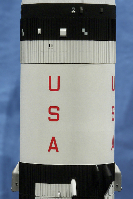
Rick Sternbach of Space Model Systems supplied the decals for this project. I did some preliminary research but Rick fleshed out the details and produced a one-off set on his Alps printer. (Later Rick produced a similar set that was printed by Microscale.) For the “UNITED STATES” and “USA” lettering I cut away all the carrier film and using a simple paper guide, spaced the letters on the tanks accordingly. Doing this certainly made these a little harder to apply but the resulting lack of decal silvering more than made up for the extra hassle.
Rick also supplied a set of decals for the Apollo Command and Service Module that I used on the payload portion of the build.
After all the decals had been applied I used Testors Metalizer Sealer as the finish coat for the major sub-assemblies. I had used this before on one of my other projects and liked the subtle sheen it gave to the model. The last sub-assemblies constructed were the four sets of air scoops and the eight vehicle hold-down assemblies, which were attached to each fin. With the completion of all of the sub-assemblies I was able to turn to final assembly of the vehicle.
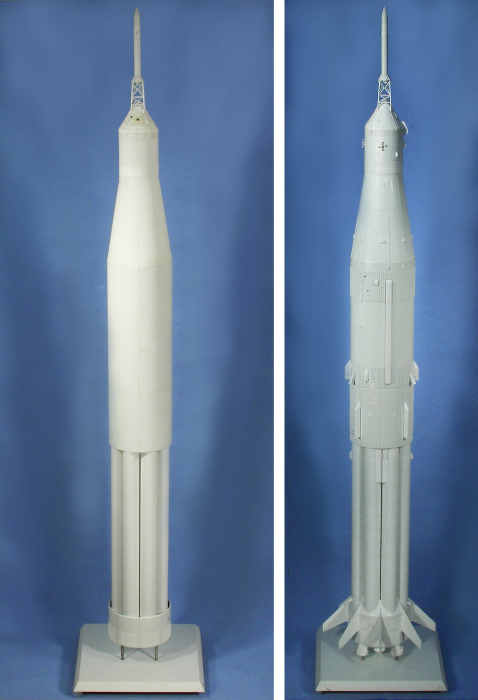
I used several different glues to attach the whole thing together. 90 and 5-minute epoxy attached the major sub-assemblies with Testors squeeze bottle cement and Aleens Tacky White Glue used to adhere the antennas and other smaller bits and pieces. When all was finished, the completed model stood about 57-1/4” tall with the outer diameter of the fins being 10-3/16” and the S-IVB cylinder diameter around 5-7/16”.
While it took over 20 years to see fruition, the actual modeling work was done between 2003 and 2010, with the majority of that over the last two and one half years. The shear size of this model taxed my workspace to the max. I had first stage fuel tanks and fins hanging from nails in the edges of shelving and upper stage cylinders placed on PVC ring stands all over my workbench. During the process I made extensive use of a “Lazy Susan” for both painting and building. In the end I figured I had cut over 3,600 pieces of styrene and used over 12 jars of Tamiya and Gunze paints. I finished the model about two weeks before the 2010 IPMS/USA National Contest and Convention in Phoenix where it won multiple awards including the Judges’ Grand Award “Best of Show”.
Reference List –
Just some of the documentation used to create the drawings for this model;
Saturn IB News Reference
GC 1044 September 1968
A PDF copy of this document is available through the University of Alabama at Huntsville Salmon Library.
Skylab Saturn IB Flight Manual
September 30, 1971
A PDF copy of this document is available through the NASA Technical Reports Server.
Apollo-Saturn AS-207 Vehicle Systems Information Drawings
Chrysler Corp. Space Division – Systems Engineering Branch
A PDF copy of this document is available in the Apogee Book “Saturn 1/1B” by Alan Lawrie.
Saturn IB Orientation – Systems Training Manual
Chrysler Corp. Space Division – Systems Engineering Branch
A PDF copy of this document is available through the University of Alabama at Huntsville Salmon Library.
NASA Apollo Command Module News Reference
North American Aviation (NAA) 1968
A PDF copy of this document is available through the NASA Technical Reports Server.
Rick Sternbach’s Space Model Systems decals are available through –
http://www.culttvmanshop.com


